Machine description
ICC424HF-CN1EN2.pdf2012-11-23
Electrical system
3
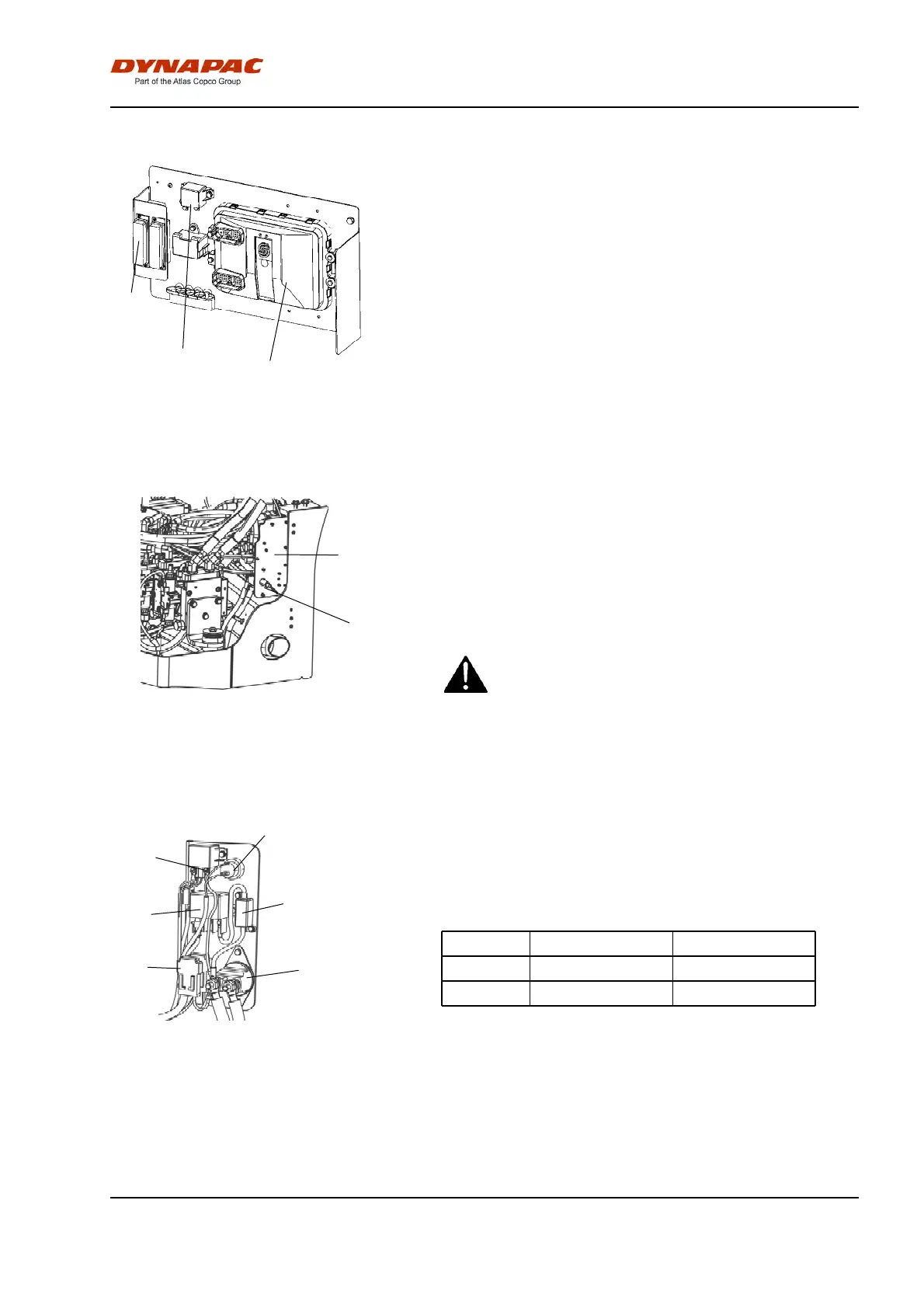
Fig. Main electrical central
1. Control unit (ECU)
2. Fuses
3. Main relay
1
2
The machine's main switchbox (1) is located on the
rear of the operator platform. There is a plastic cover
over the distribution box and fuses.
On the plastic cover there is a 24V socket.
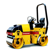
Fig. Battery bay
1. Master switch
2. Main fuse panel
1
2
The fuses in the engine compartment are located
alongside the master switch.
The roller is equipped with 24 V electrical system and
an AC alternator.
Connect the correct polarities (ground) to the
battery. The cable between the battery and the
alternator must not be disconnected when the
engine is running.
Connect the correct polarities (ground) to the
battery. The cable between the battery and the
alternator must not be disconnected when the
engine is running.
5
Fig. Main fuse panel
1. Battery disconnector
2. Preheating relay (100A)
3. Fuse (F21) (125A)
4. Starter relay (50A)
5.Fuses (F13, F10, F22)
6. Power socket 24V
6
4
3
1
2
The main fuse panel is located behind the left engine
compartment door.
The fuses are placed in the order shown below,
starting by the plate.
F13 Engine ECU (30A)F13 Engine ECU (30A)
F10 Main fuse (50A)F10 Main fuse (50A)
F22 Cab (50A)F22 Cab (50A)
41