Machine description
ICC424HF-CN1EN2.pdf 2012-11-23
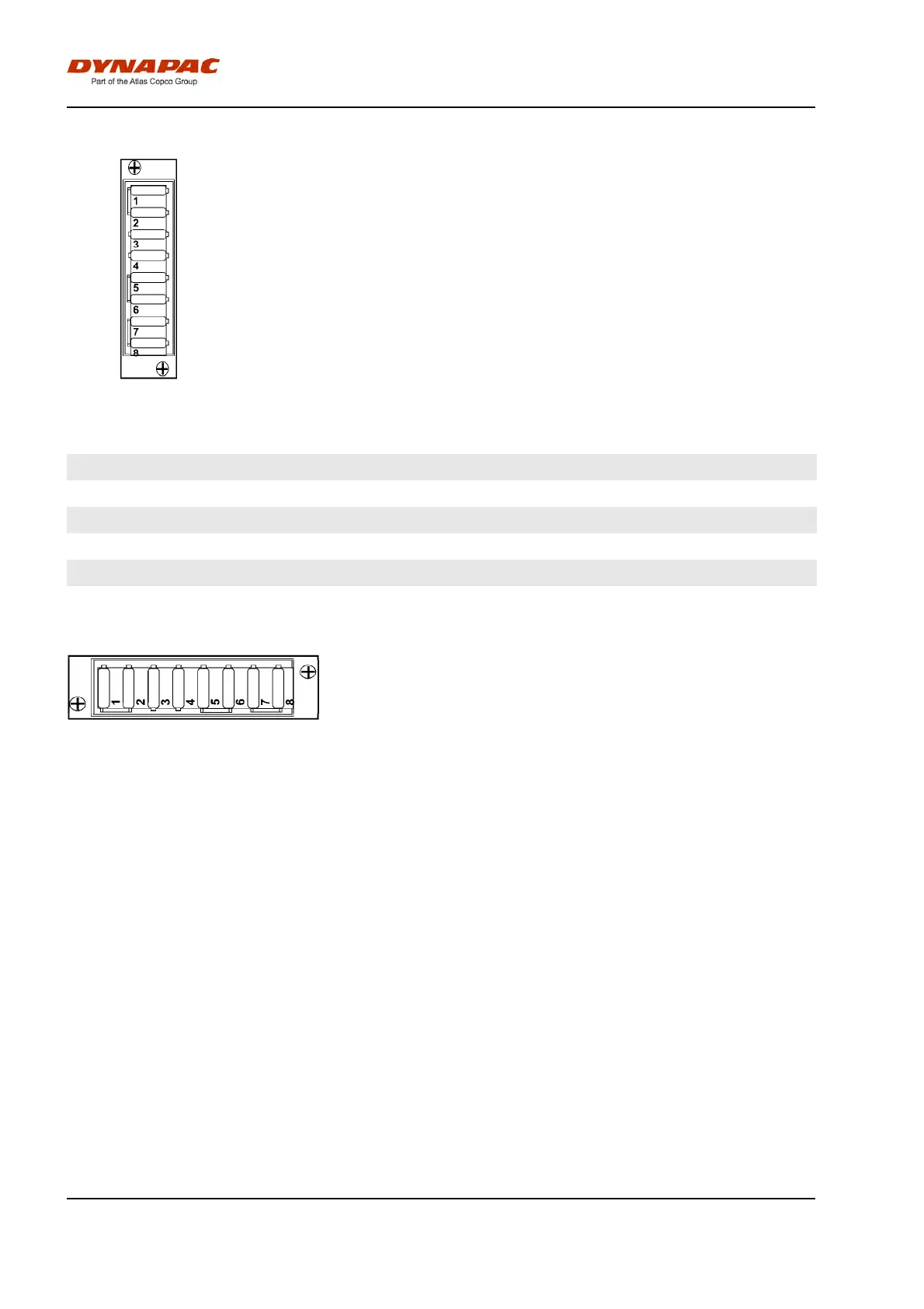
Fuses
Fig. Fuse box
The figure shows the position of the fuses.
The table below gives fuse amperage and function. All
fuses are flat pin fuses.
Fuse box (F1)Fuse box (F1)
1.
Main relay (F1.1) 5A
5.
Power group 3, Main ECU (F1.5) 20A
1.
Main relay (F1.1) 5A
5.
Power group 3, Main ECU (F1.5) 20A
2.
Supply, Main ECU, I/O unit, Display (F1.2) 5A
6.
Power group 4, Main ECU (F1.6) 20A
2.
Supply, Main ECU, I/O unit, Display (F1.2) 5A
6.
Power group 4, Main ECU (F1.6) 20A
3.
Power group 1, Main ECU (F1.3) 10A
7.
24V outlet, Lighting for tachograph (F1.7) 10A
3.
Power group 1, Main ECU (F1.3) 10A
7.
24V outlet, Lighting for tachograph (F1.7) 10A
4.
Power group 2, Main ECU (F1.4) 10A
8.
Accessory ECU, Driving lights (F1.8) 20A
4.
Power group 2, Main ECU (F1.4) 10A
8.
Accessory ECU, Driving lights (F1.8) 20A
Fuses in cab
Fig. Cab roof fuse box (F7)
1. Interior lighting 10A1. Interior lighting 10A
2. CD/Radio 10A2. CD/Radio 10A
3. AC condensor 15A3. AC condensor 15A
4. Cab fan 15A4. Cab fan 15A
5. Windscreen wiper/washers,
front
10A5. Windscreen wiper/washers,
front
10A
6. Windscreen wiper/washers,
rear
10A6. Windscreen wiper/washers,
rear
10A
7. Reserve7. Reserve
8. Reserve8. Reserve
The electrical system in the cab has a separate fuse
box located on the front right side of the cab roof.
The figure shows fuse amperage and function.
All fuses are flat pin fuses.
42