Operation
ICC424HF-CN1EN2.pdf2012-11-23
2
3
4
1
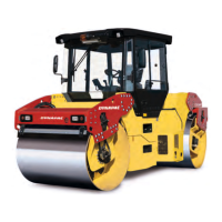
Fig. Control panel
1. Parking brake
2. F/R lever
3. Speed control
4. Working mode
Release the parking brake button (1) by sliding the
red lock on the button backwards and changing
the postion of the lever. Remember that the roller
can start rolling, if it is on a slope.
Release the parking brake button (1) by sliding the
red lock on the button backwards and changing
the postion of the lever. Remember that the roller
can start rolling, if it is on a slope.
Machine with gear change in the speed
potentiometer.
Activate the button to get Working mode (4).
Position the speed control (3) in suitable position, 0-12
km/h (0-8 mph).
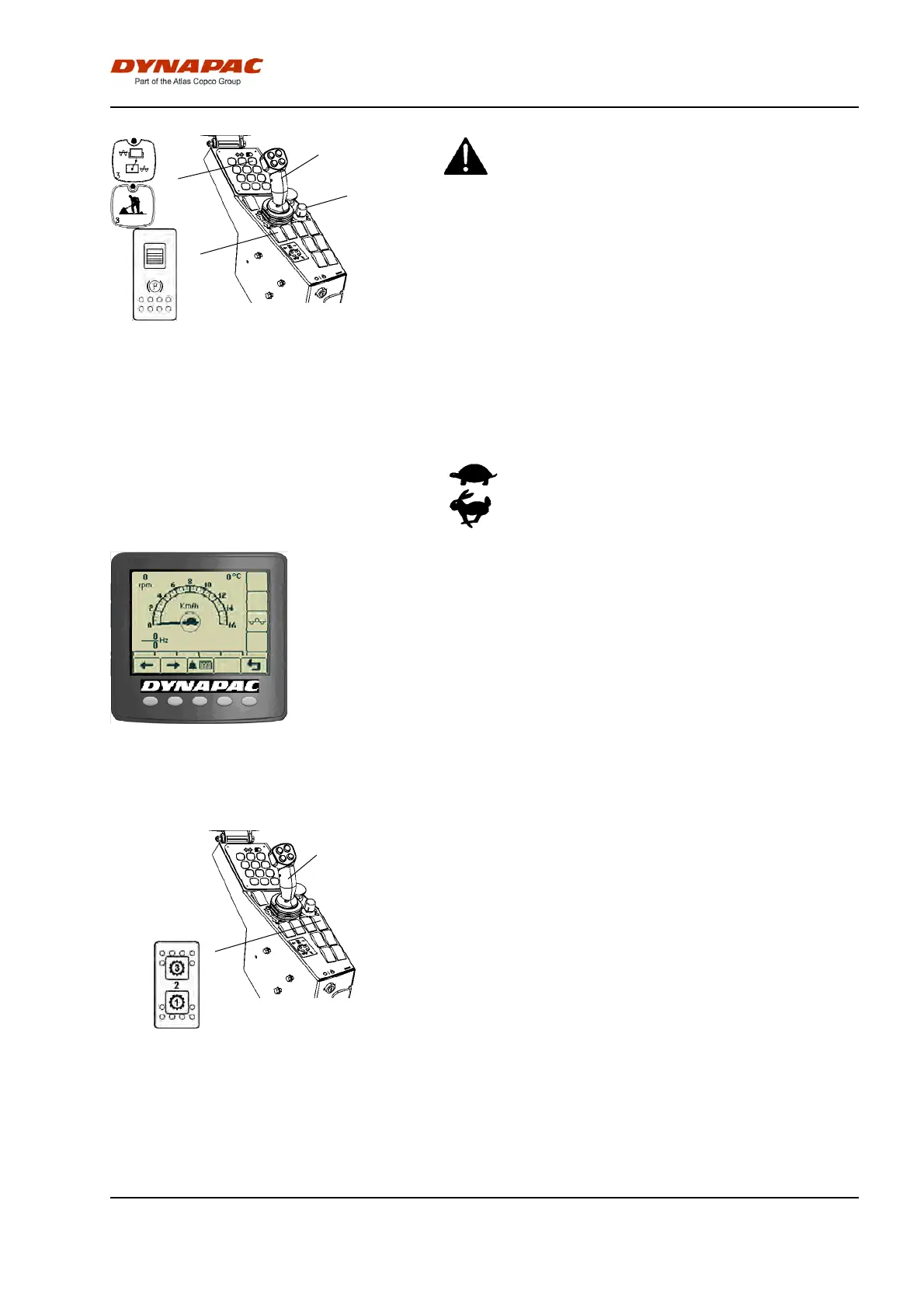
The machine's gear position is shown in the center of
the speedometer. Select the gear/speed for the task:
= slow= slow
= fast= fast
Figure. The display shows the selection
in the middle (tortoise or rabbit).
Carefully move the forward/reverse lever (2) forwards
or backwards, depending on which direction of travel
is required.
Speed increases as the lever is moved away from the
neutral position.
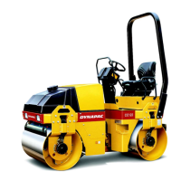
Machine with gear change in separate 3-position
switch (gear position switch)
Fig. Control panel
1. Gear position switch
2. Forward/Reverse lever
2
1
Position 1: Used for maximum hill-climbing capacity
during vibratory compaction
Position 2: Normal position
Position 3: Used for maximum transport speed or for
high speed during smooth rolling without vibration
Carefully move the forward/reverse lever (2) forwards
or backwards, depending on which direction of travel
is required.
The speed increases as the lever is moved away from
the neutral position.
51