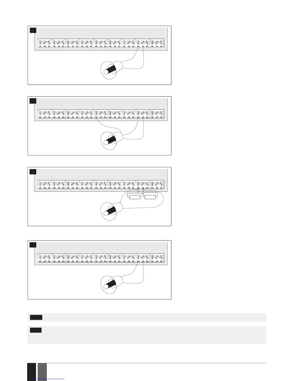
2.3.3. Siren
RED +
BLACK -
BELL-
BELL+
SIREN/BELL
1A max.
8
Piezo siren
1 Connect positive siren wire (red) to BELL+ ter-
minal.
2 Connect negative siren wire (black) to BELL-
terminal.
+12V
GND
BELL
BELL-
COM
BELL+
SIREN/BELL
1A max.
9
Self-contained siren
1 Connect negative GND siren wire to COM termi-
nal.
2 Controlling BELL siren wire must be connected
to BELL- terminal.
3 Connect positive +12V siren wire to BELL+ ter-
minal.
RED +
BLACK -
BELL-
BELL+
SIREN/BELL
1A max.
3,3kΩ 3,3kΩ
10
Siren status monitoring
NOTE: Siren status monitoring feature supervises
the resistance across BELL+ and BELL- terminals.
The resistance must be ranging from 1k through
3,3k, otherwise the system will indicate system
fault. In order to view the siren resistance value,
please refer to Diagnostic Management feature
available on ELDES Conguration software.
RED +
BLACK -
BELL-
BELL+
SIREN/BELL
1A max.
11
No siren status monitoring
If the siren status monitoring feature is not re-
quired, do not connect any resistor in parallel and
disable siren fault indication on the keypad (see 29.
INDICATION OF SYSTEM FAULTS).
See also 20. SIREN/BELL.
NOTE: BELL- is the commuted terminal intended for siren control.
NOTE: Siren status monitoring feature supervises the resistance across BELL+ and BELL- terminals. The resistance must be ranging from
1k through 3,3k, otherwise the system will indicate system fault. In order to view the siren resistance value, please refer to Diagnostic
Management feature available on ELDES Conguration software.