12
Supported iButton key model: Maxim/Dallas
DS1990A
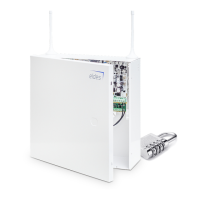
The iButton key reader can be installed with buzzer
or separately. The buzzer is intended for audio in-
dication of exit/entry delay countdown providing
short beeps.
1 Connect iButton key reader brown and white
wires to 1-Wire interface: COM and DATA termi-
nals respectively.
2 Connect buzzer‘s negative terminal wire to BUZ-
and positive terminal wire to BUZ+.
NOTE: The installation of buzzer is not necessary if EKB2/EKB3 keypad is used.
ATENTION: The cable length for connection to 1-Wire interface can be up to 30m (98.43ft) max.
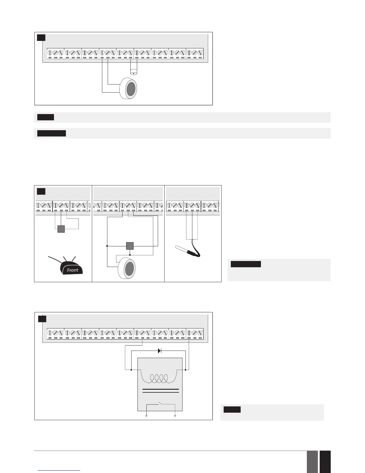
2.3.5. Temperature Sensor and iButton Key Reader
Supported iButton key model: Maxim/Dallas DS1990A
Supported temperature sensor model: Maxim/Dallas DS18S20, DS18B20
COM
DATA
+5V
GND
DATA
+5V
iButton
key reader
DS1990A
Temperature
sensor
DS18S20
white
brown
COM
DATA
+5V
GND +5V
DATA
Temperature sensor
DS18S20
GND DATA +5V
COM
DATA
+5V
black
yellow
red
Digital thermometer
with 3m (9.84ft) wire
Vinson DS18B20
13
1 Depending on the model, connect temper-
ature sensor GND/black wire, DATA/yellow
wire, +5V/red wire terminals to 1-Wire inter-
face: COM, DATA and +5V terminals respec-
tively.
2 When connecting iButton key reader in par-
allel to temperature sensor, connect iButton
key rea der terminal wires to COM and DATA
terminals respectively.
ATENTION: The cable length for connec-
tion to 1-Wire interface can be up to 30m
(98.43ft) max.
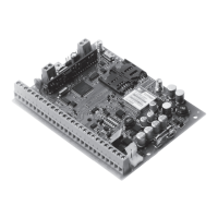
2.3.6. Relay Finder (for example, model 40.61.9.12) with Terminal Socket (for example, model 95.85.3) to PGM Output
Example of relay wiring for negative PGM output control
A1
C1
AUX+
A2
COIL
RELAY
14
1 Wire up relay A1 terminal to PGM output Cx and
A2 terminal to AUX+.
2 In addition, connect the switching diode to re-
lay‘s A2 and A1 terminals.
NOTE: We highly recommend using switch-
ing diode model 1N4148 or similar.