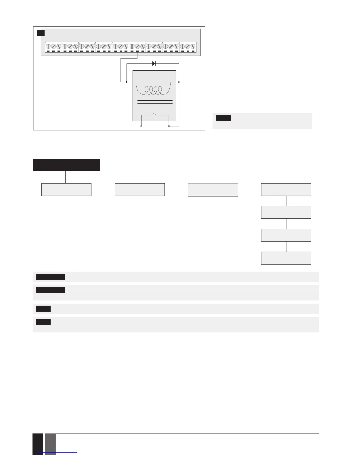
Example of relay wiring for positive PGM output control
A1
C1
AUX+
A2
COIL
RELAY
15
1 Wire up relay A1 terminal to PGM output‘s Cx
terminal and A2 terminal to AUX+ and one of
the relay‘s switch contacts: NC or NO.
2 In addition, connect the switching diode to re-
lay‘s A2 and A1 terminals.
NOTE: We highly recommend using switch-
ing diode model 1N4148 or similar.
2.3.7. RS485
Serial Wiring Method
ESIM384
a
b c
d
e
f
g
EKB2/EKB3 EKB2/EKB3
EKB2/EKB3
EKB2/EKB3
EPGM1
EPGM1
ELAN3-ALARM
Max. cable length: a+b+c+d+e+f+g= up to 100m (328.08ft)
ATTENTION: The cable length must not exceed 100m (328.08ft) in total.
ATTENTION: When wiring more than 1 keypad and/or EPGM1 module, please ensure that the set address of each keypad and/or EPGM1
module is dierent.
NOTE: If necessary, the RS485 devices can be powered from an external 12-14V DC power supply instead of AUX+ and AUX- terminals
NOTE: You may connect only 1 EKB2/EKB3 keypad or a mixed combination of EKB2 and EKB3 keypads. The combination can consist of
up to 4 keypads in total.
For more details on RS485 interface, please refer to 32.1. RS485 Interface