• LOGICAL ID: This displays the logical address assigned to the input.
• PHYS.ADDRESS: This shows the physical address of the input.
• TYPE: This indicates the input use method.
• DESCRIPTION: This is the alphanumeric label used to identify the device more easily.
• STATE: This indicates the input status according to the following table:
= Open input
= Open input memory
= Alarm memory
= Tamper input (sabotage)
= Input excluded/isolated
= Inhibited (temporarily excluded)
= Close (input in stand-by)
= Jamming
The following buttons appear under underneath:
• CSV: This can be used to export the inputs list to a “.csv” file, which can be opened with a spreadsheet.
• PDF, which exports the list of inputs to a PDF file.
• R, reset the open input memory.
The < and > buttons in the bottom right are used to navigate between table pages.
6.1.8 Output
This enables and disables individual outputs.
It is accessed through the DIAGNOSTIC→ INPUT/OUTPUT menu.
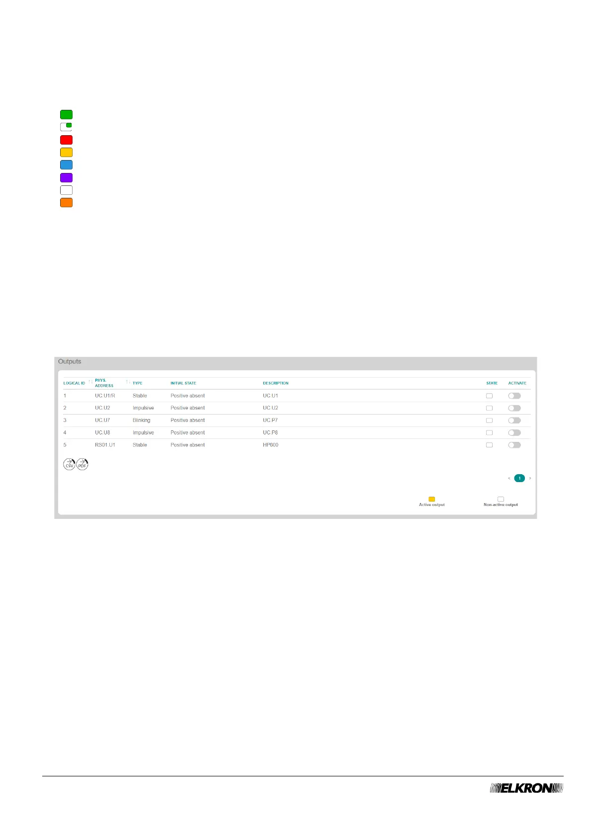
Figure 117 - Manual activation of the outputs
The following information is included in the table concerning the outputs.
• LOGIC ID: This shows the logical address assigned to the output.
• PHYS.ADDRESS: This shows the physical address of the output.
• TYPE: This indicates the output use method.
• INITIAL STATE: This indicates the status of the output when it is at stand-by (not activated).
• DESCRIPTION: This is the alphanumeric label used to identify the output more easily.
• STATE: This indicates the real-time status of the output.
• ACTIVATE: The status of the output can be switched by acting on the switch relative to the
respective output.