C4 Maintenance 6. Joint #2
88 C Series Maintenance Manual Rev.2
6.4 Joint #2 - Replacing the Electromagnetic Brake
Removal: Joint #2 Electromagnetic brake
1. Remove the Joint #2 electromagnetic brake.
For details, refer to C4 Maintenance: 6.1 Joint #2 – Replacing the Motor,
Installation steps (1) through (8).
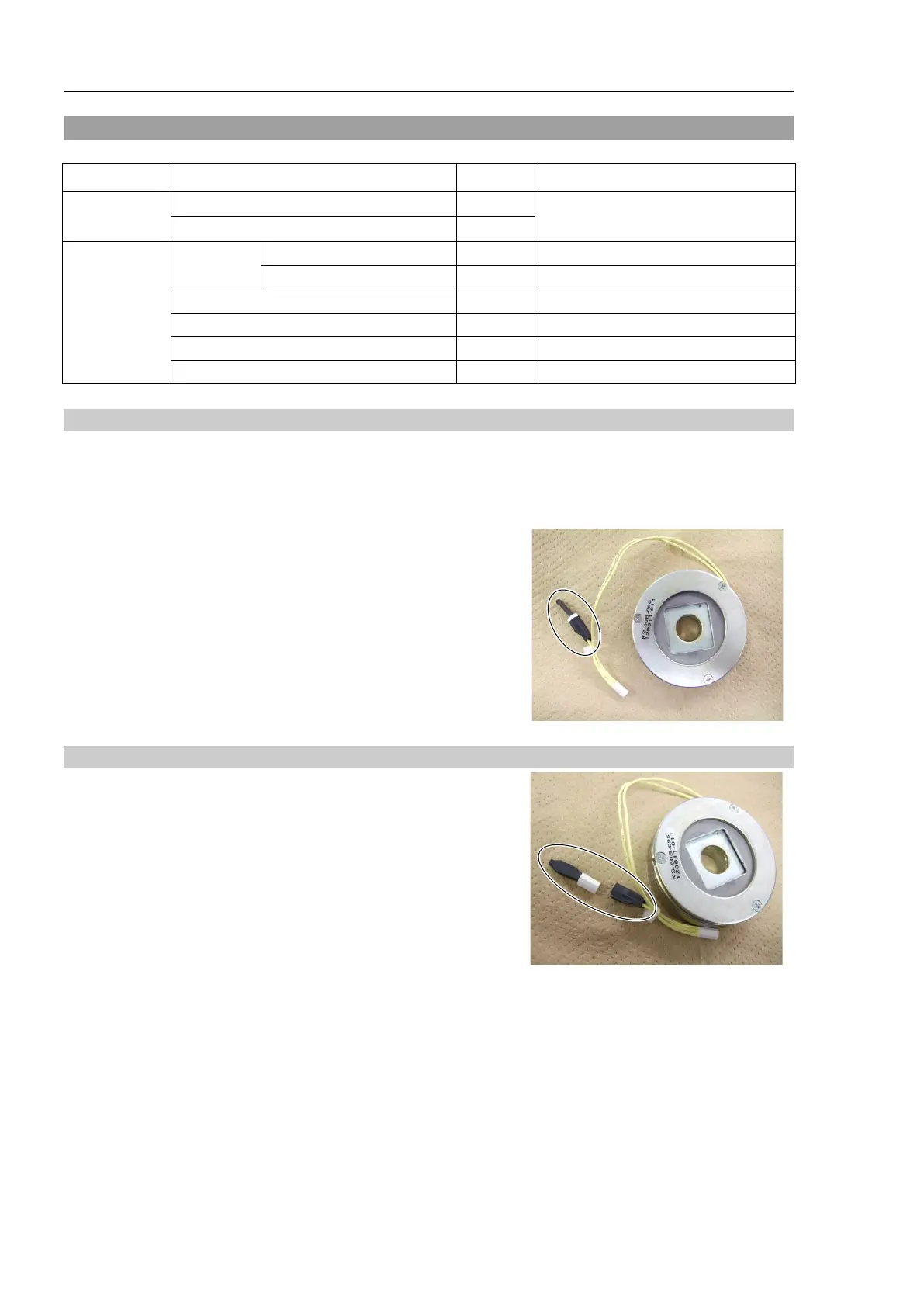
2. Disconnect the following connectors.
Connector: D (for noise dissipative diode)
Installation: Joint #2 Electromagnetic brake
1. Connect the following connector to the electromagnetic brake
connector.
Connector: D (for noise dissipative diode)
2. Assemble the Joint #2 electromagnetic brake and mount the motor unit.
For details, refer to C4 Maintenance: 6.1 Joint #2 – Replacing the Motor,
Installation steps (2) through (9).
Maintenance
Joint #2 electromagnetic brake
For the part code, refer to the 17. C4
Tools
Hexagonal
width across flats: 2.5 mm
For M5 hexagon socket set screw
For M4 hexagon socket head cap bolt

 Loading...


