C4 Maintenance 9. Joint #5
C Series Maintenance Manual Rev.2 121
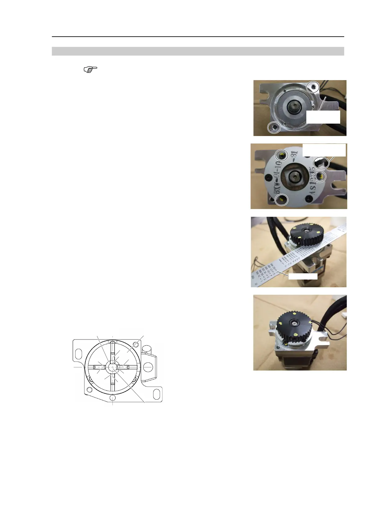
Installation: Joint #5 Motor
When tightening hexagon socket head cap bolts, refer to the 2.4 Tightening Hexagon Socket
Head Cap Bolts.
1. Install the motor plate to the Joint #5 motor.
Hexagon socket head cap bolts: 2-M4×12
Tightening torque: 4.9 N·m (50 kgf·cm)
Be careful of the direction of the motor plate. (See the photo.)
2. Mount the Joint #5 electromagnetic brake to the Joint #5 motor
unit.
Hexagon socket set screws: 3-M2.5×10
Be careful of the direction of the Joint #5 electromagnetic brake
wiring. (See the photo.)
Electromagnetic
brake wiring
3. Mount the drive boss and the pulley 1 to the Joint #5 motor unit.
Set the drive boss and the pulley 1 so that their surfaces become
flat.
Hexagon socket set screws: 2-M3×8 (with a brass bushing)
Fix the pulley 1 and the motor shaft.
Leave 0.5 mm for the electromagnetic brake.
Hexagon socket set screws: 2-M3×8 (with a brass bushing)
Set the set screws as indicated below.
Pulley
Motor shaft
Drive boss
A : Pulley and
motor shaft fixing screws
B : Pulley and
drive boss fixing screws
C : Bushing
D : Flat face for motor shaft
E : Flat face for drive boss
A
A
B
C
C
B
D
E