C8 Maintenance 10. Joint #6
C Series Maintenance Manual Rev.2 389
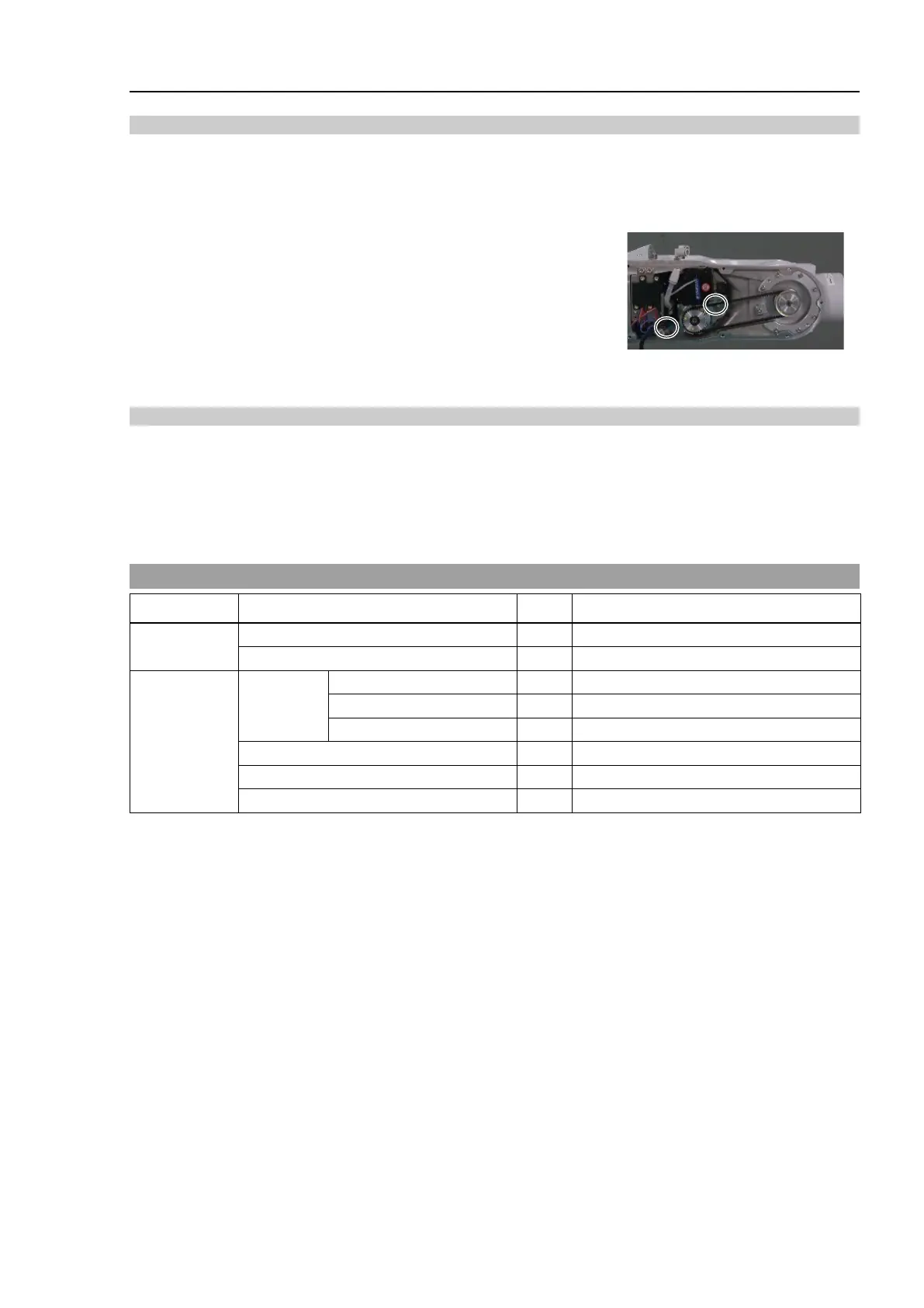
Removal: Joint #6 Timing belt
1. Turn OFF the Controller power.
2. Remove the Arm #4 side cover.
For details, refer to C8 Maintenance: 3. Covers.
3. Loosen the Joint #6 motor unit set screw.
Hexagon socket head cap bolt: 2-M4×15 (with a plain washer)
4. Remove the Joint #6 timing belt.
Installation: Joint #6 Timing belt
1. Place the Joint #6 timing belt around the pulley 1 and 2 of the Joint #6.
2. Secure the Joint #6 motor unit.
For details, refer to C8 Maintenance: 10.1 Joint #6 – Replacing the Motor, Installation steps (5) to (6) and
(10) to (11).
10.4 Joint #6 - Replacing the Electromagnetic Brake
Name Qty. Note
Maintenance
2172928 (Common to Joints #4, #5, #6)
Tools
Hexagonal
wrench
For M4 hexagon socket set screws
width across flats: 2.5 mm
For M3 hexagon socket head cap bolts
For M4 hexagon socket head cap bolts
Cross-point screwdriver (#2)
For cross recessed head screws
For adjusting the pulley position
* The belt tensile jig is an assembly jig. Use the jig when adjusting belt tension.
The brake is mounted on each joint to prevent the arm from lowering due to its own weight while the Controller
power is OFF or the motor is OFF status. The brake does not work during replacement.
Be careful when performing maintenance work.