C8 Maintenance 5. Joint #1
306 C Series Maintenance Manual Rev.2
5.2.4 Joint #1 - Replacing the Electromagnetic Brake
(M/C Cable Downward)
Name Qty. Note
Maintenance
Parts
Electromagnetic brake (Joint #1, #2)
J1 brake positioning jig *
Tools
Hexagonal wrench
(width across flats: 3 mm)
1 For M4 hexagon socket head cap bolt
Cross-point screwdriver (#2)
For cross recessed head screws
For tightening torque control
* The J1 brake positioning jig is an assembly jig. Use the jig in relevant maintenance steps.
The brake is mounted on each joint to prevent the arm from lowering due to its own weight while the Controller
power is OFF or the motor is OFF status. The brake does not work during replacement. Be careful when
performing maintenance work.
Removal: Joint #1 Electromagnetic brake (M/C Cable Downward)
1. Remove the Joint #1 brake plate from the Joint #1 motor unit.
For details, refer to C8 Maintenance: 5.2.1 Joint #1-Replacing the Motor (M/C Cable Downward),
Removal steps (1) to (6).
Do not disconnect the connector BT1. If the connector is disconnected, perform calibration.
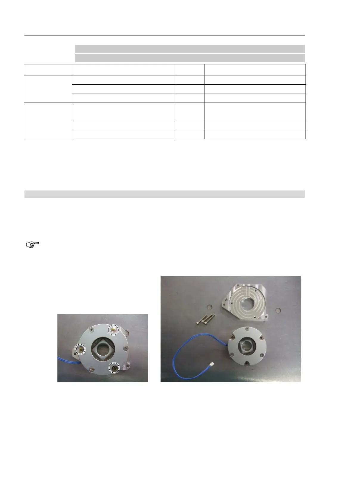
2. Remove the Joint #1 brake from the brake plate.
Hexagon socket head cap bolts: 3-M4×25