C8 Maintenance 5. Joint #1
C Series Maintenance Manual Rev.2 307
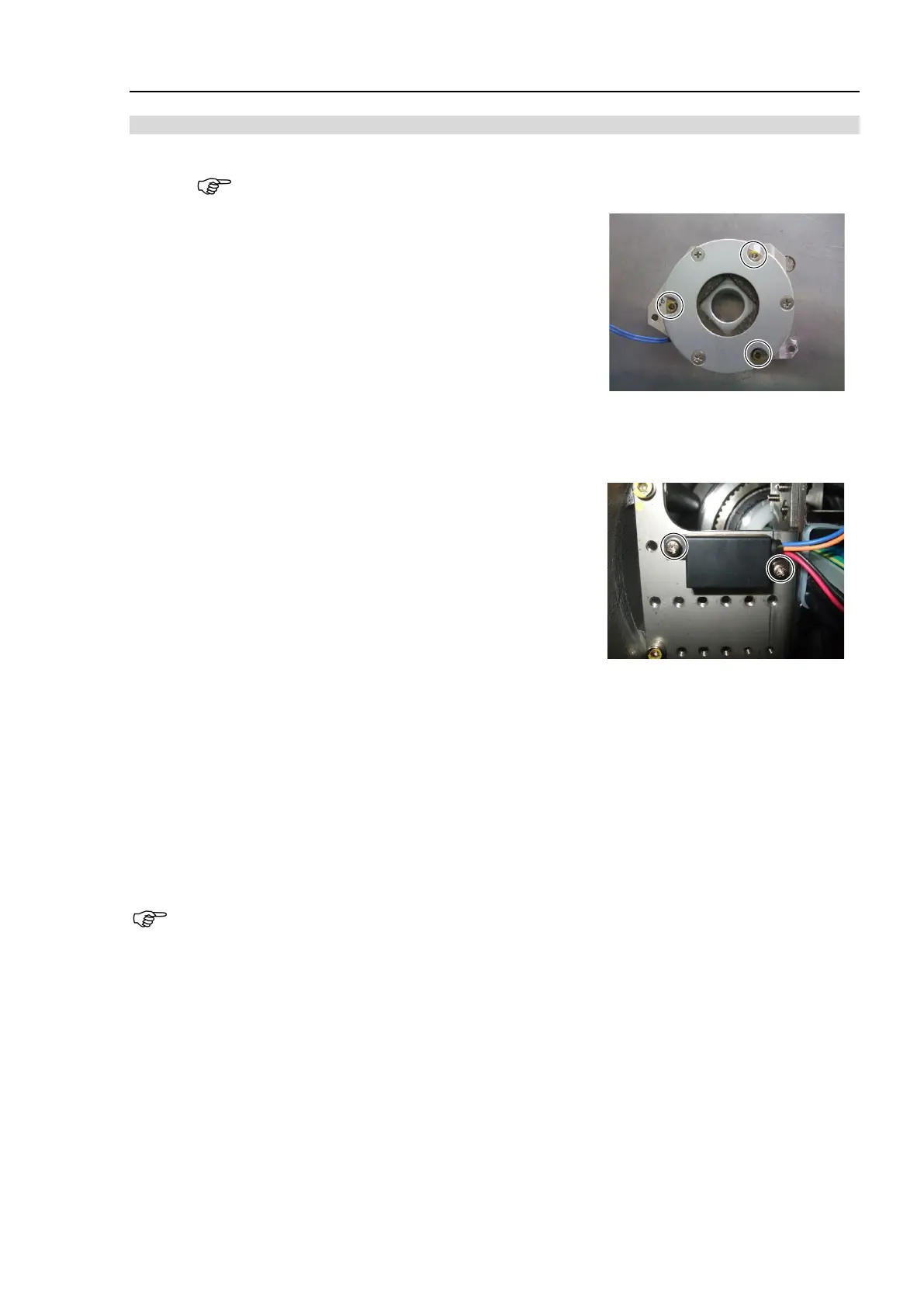
Installation: Joint #1 Electromagnetic brake (M/C Cable Downward)
When tightening hexagon socket head cap bolts, refer to the 2.4 Tightening Hexagon Socket
Head Cap Bolts.
1. Install the Joint #1 brake to the brake plate.
Hexagon socket head cap bolts: 3-M4×25
Tightening torque: 4.0 ± 0.2 N·m
Be careful of the assembly direction of the Joint #1
electromagnetic brake. (See the photo)
2. Mount the Joint #1 brake plate to the Joint #1 motor unit.
For details, refer to C8 Maintenance: 5.1.1 Joint #1 - Replacing the Motor (M/C Cable Backward),
Installation step (4).
3. Install the brake power supply to the plate. Make sure to install
the brake power supply so that the cables will be in the direction
as shown in the photo.
Cross recessed head screws with washer: 2-M3×6
Tightening torque: 0.45 ± 0.1 N·m
4. Connect the M/C cable connectors.
Connector: X11, X010, BT1, BR011
5. Install the following covers.
Connector plate (M/C cable downward)
Base cover (M/C cable downward)
Base maintenance cover
For details, refer to C8 Maintenance: 3 Covers.
If you disconnected the connector BT1 in the removal steps, perform calibration.