C8 Maintenance 3. Covers
C Series Maintenance Manual Rev.2 223
3.12 Connector Sub Plate
CAUTION
■
remove the connector sub plate forcibly. It may result in damage to the
cables, disconnection, and/or contact failure. These are extremely hazardous
and may result in electric shock and/or improper function of the robot system.
■
When removing the connector sub plate, make sure to remove
all connectors of
the connector plate and the
M/C cable. Removing only the connector sub plate
may result in damage to the cables, disconnection, and/or contact failure. These
are
extremely hazardous and may result in electric shock and/or improper function
■
When installing the connector sub plate, be careful not to get the cables caught in
it or bend them forcibly to push into the cover.
Unnecessary strain on cables may result in damage to the cables, disconnection,
and/or contact failure. These are extremely hazardous and may result in electric
shock and/or improper function of the robot system.
When routing the cables, check the cable l
ocations at removing the connector sub
plate. Be sure to place the cables back to their original locations.
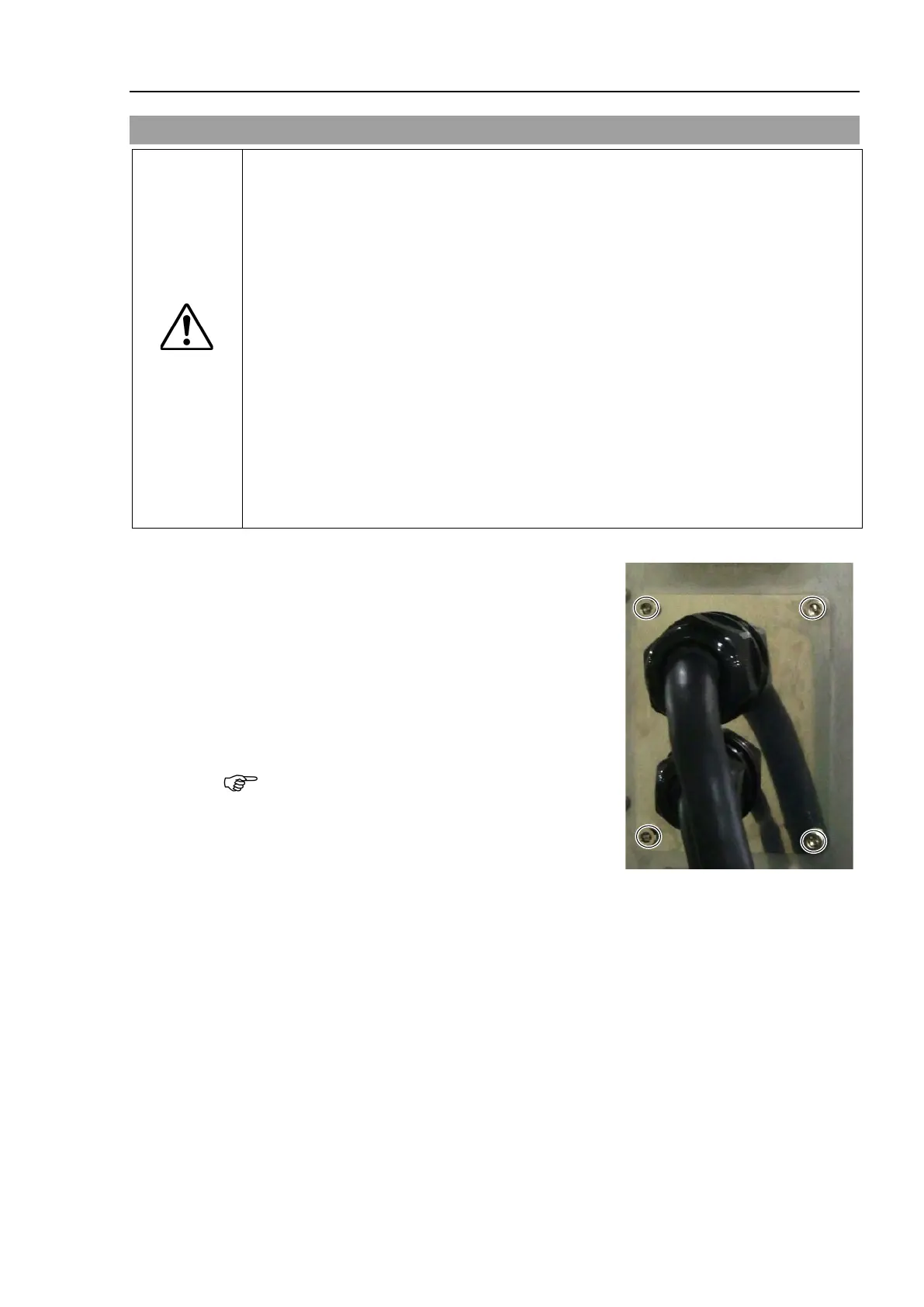
Remove the bolts and then remove the connector sub
plate.
Hexagon socket head cap bolts: 4-M4×10
Hexagon socket head cap bolts:
4-M4×10 (with a seal washer)
Remove the base sub plate gasket together.
The gasket has the spacers.
Be careful not to lose the seal washers and spacers.