C8 Maintenance 8. Joint #4
364 C Series Maintenance Manual Rev.2
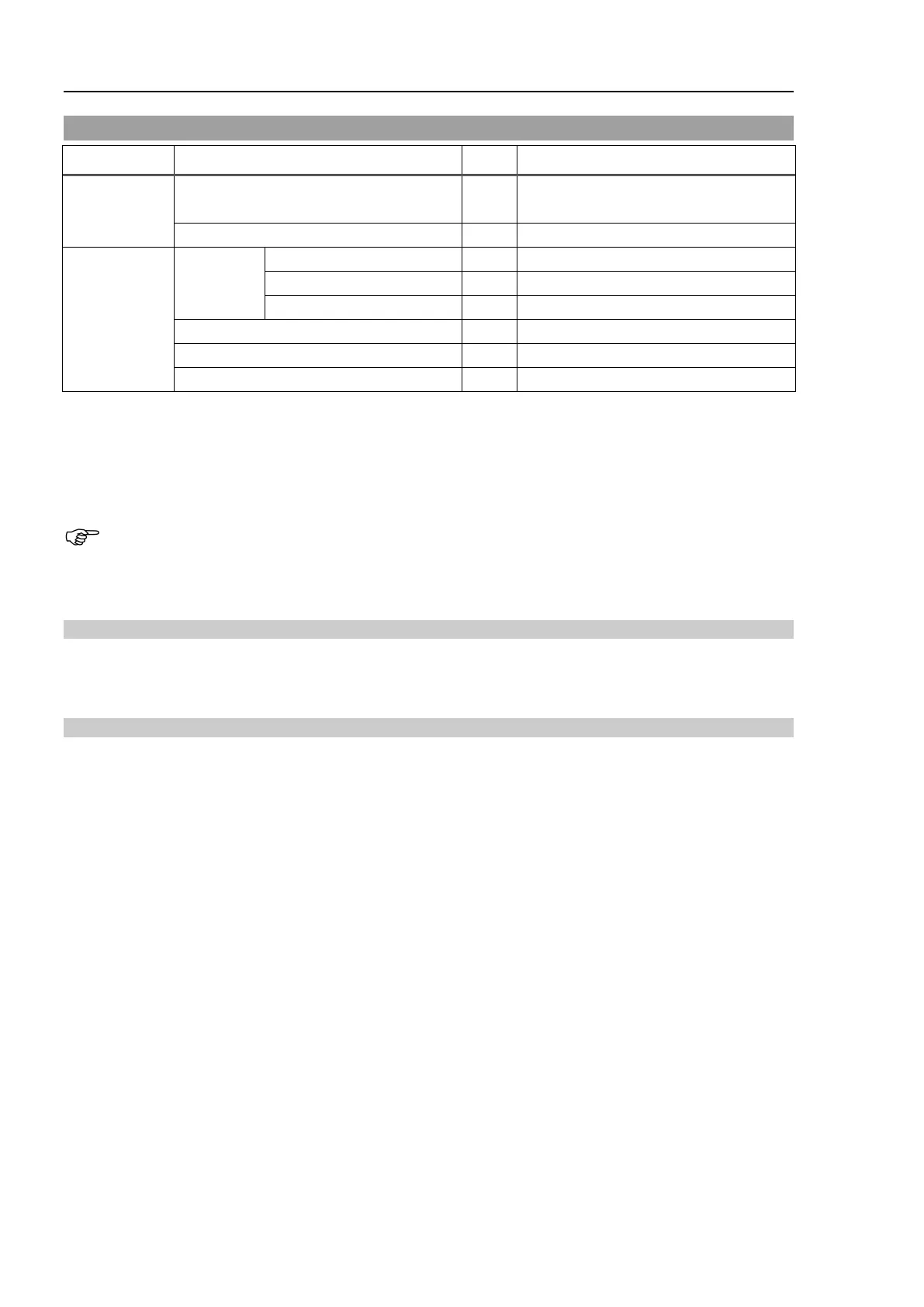
8.4 Joint #4 - Replacing the Electromagnetic Brake
Name Qty. Note
Maintenance
Parts
Electromagnetic brake 1
2172928
(common for Joints #4, #5, #6)
Tools
Hexagonal
wrench
For M4 hexagon socket set screws
width across flats: 2.5 mm
For M3 hexagon socket head cap bolts
For M4 hexagon socket head cap bolts
Cross-point screwdriver (#2)
For cross recessed head screws
For adjusting the drive boss position
* The belt tensile jig is an assembly jig. Use the jig when adjusting belt tension.
The brake is mounted on each joint to prevent the arm from lowering due to its own weight while the
Controller power is OFF or the motor is OFF status. The brake does not work during replacement.
Be careful when performing maintenance work.
The electromagnetic brakes are common for Joints #4, #5, and #6.
The Joints #5 and #6 electromagnetic brakes have an identification label for preventing misconnection
of the connectors. The label is not necessary for the Joint #4 electromagnetic brake. (There is no
connector identification label for the Joint #4.)
Removal: Joint #4 Electromagnetic brake
1. Remove the Joint #4 electromagnetic brake.
For details, refer to C8 Maintenance: 8.1 Joint #4 – Replacing the Motor, Removal steps (1) through (8).
Installation: Joint #4 Electromagnetic brake
1. Mount the Joint #4 electromagnetic brake to the Joint #4 motor unit.
For details, refer to C8 Maintenance: 8.1 Joint #4 – Replacing the Motor, Installation steps (2) through (11).