C4 Maintenance 9. Joint #5
C Series Maintenance Manual Rev.2 119
9.1 Joint #5 - Replacing the Motor
The brake is mounted on the Joint #5 to prevent the arm from lowering due to its own weight while the Controller
power is OFF or the motor is OFF status. However, the brake does not work during replacement.
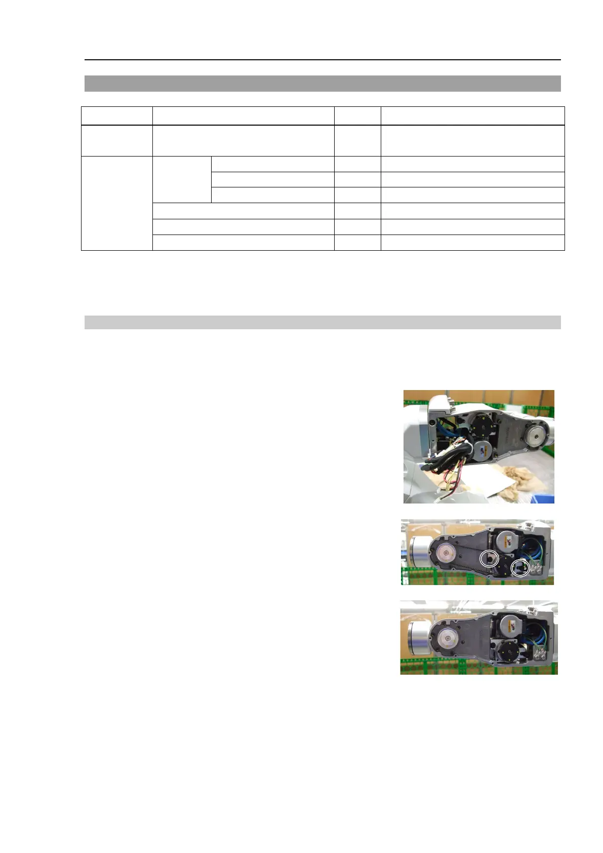
Removal: Joint #5 Motor
1. Turn OFF the Controller power.
2. Remove the Arm #4 side cover.
For details, refer to C4 Maintenance: 3. Covers.
3. Pull out the cables from the Arm #4 and disconnect the following
connectors.
Connectors: X052, X152, BT52, BR052
4. Loosen the bolts securing the Joint #5 motor unit and remove the
belt.
Hexagon socket head cap bolts: 2-M4×15 (with a plain washer)
5. Remove the Joint #5 motor unit.
Hexagon socket head cap bolts: 2-M4×15 (with a plain washer)
Name Quantity Note
Maintenance
AC servo motor 50 W 1
For the part code, refer to
17. C4
Maintenance Part Code.
Tools
Hexagonal
wrench
width across flats: 1.5 mm
For M3 hexagon socket set screws
For M2.5 hexagon socket head cap bolts
For M4 hexagon socket head cap bolts
For belt tension adjustment

 Loading...


