C4 Maintenance 9. Joint #5
C Series Maintenance Manual Rev.2 125
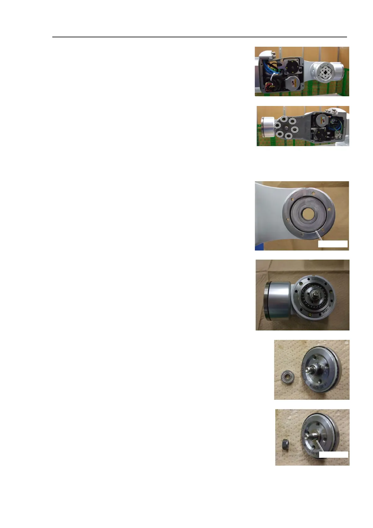
10. Remove the Joint #6 flange unit.
Hexagon socket head cap bolts: 6-M3×15
11. Loosen the set screws securing the Joint #5 reduction gear unit and
remove the Arm #5 unit.
Hexagon socket head cap bolts: 6-M3×15
The parts are greased. Wipe grease on the parts while removing
them.
12. Remove the O-rings.
The O-rings are on the installation surfaces of the Arm #4 and #5.
The O-ring of the Arm #4 is on the Arm #4 plate which was
removed in the step (9).
For the O-ring of the Arm #5, see the photo on the right.
13. Remove the wave generator from the reduction gear unit.
If it is difficult to remove the wave generator unit, install the
removed pulley 2 to the shaft and remove the parts.
When removing the wave generator, the bearing on the end of the
shaft comes off together. Do not lose the bearing.
The parts are greased. Wipe grease on the parts while removing
them.
14. Remove the wave generator from the shaft.
Remove the bearing. The bearing will be used again. Be careful
not to lose it.
There is a washer between the nut and the wave generator.
Be careful not to lose it.
The parts are greased. Wipe grease on the parts while removing
them.
Open-end wrench width for the shaft: 7 mm
Open-end wrench width for the nut: 8 mm

 Loading...


