C8 Maintenance 6. Joint #2
C Series Maintenance Manual Rev.2 315
3. Mount the drive boss and the pulley 1 to the Joint #2 motor unit.
Insert the pulley 1 so that the set screw is aligned to the flat
surface of the motor shaft.
Fix the pulley 1 and the motor shaft.
Leave 0.5 mm between the pulley 1 and the electromagnetic brake.
The countersunk screw of the electromagnetic brake is proj
Using the feeler gauge (0.5 mm), leave a space for the projection.
If there is no space for the projection, the parts may chafe while the motor is driving and it may result
in breakage.
Hexagon socket set screws: 2-M5×12
Tightening torque: 3.9 ± 0.2 N·m
If the drive boss and the pulley 1 are removed:
Align the end faces of the drive boss and the pulley 1, and then fix them.
Hexagon socket set screws: 2-M5×8 (with a brass bushing)
Tightening torque: 3.9 ± 0.2 N·m
If the screw positions are incorrect or the bushing is not set, it may cause damage on the side of the
part and may result in the part being unable to be removed.
Set the set screws to the positions indicated in the right figure.
A: Pulley and motor shaft screws
(D-cut part of the motor shaft × 2)
B: Pulley and drive boss screws
Do not remove these screws.
C: Bushing
Pulley
Drive boss
A
A
C
B
B
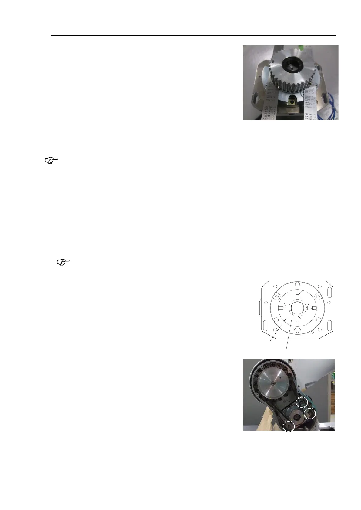
4. Put the Joint #2 motor unit in the Arm #1.
5. Set the timing belt around the pulley 1 and the pulley 2 and fix it
temporarily.
Check that the teeth of the timing belt engage with these of the
pulley.
As a rough guide of temporary fixing, check that the motor unit
can be moved by hand, and it does not tilt when being pulled. If
the belt is too loose or too tight, it will not have proper tension.
Hexagon socket set screws: 3-M5×25 (with a plain washer)