C8 Maintenance 8. Joint #4
348 C Series Maintenance Manual Rev.2
Installation: Joint #4 Motor
When tightening hexagon socket head cap bolts, refer to the 2.4 Tightening Hexagon Socket
Head Cap Bolts.
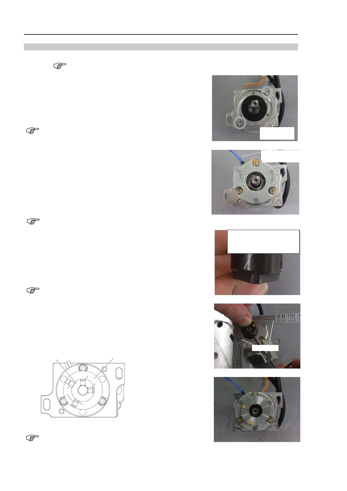
1. Install the motor plate to the Joint #4 motor.
Hexagon socket head cap bolts: 2-M4×10
Tightening torque: 4.0 ± 0.2 N·m
Be careful of the assembly direction of the motor plate.
(See the photo.)
2. Mount the Joint #4 electromagnetic brake to the Joint #4 motor
unit. Set the spacers between the hexagon socket set screws and
the Joint #4 electromagnetic brake.
Hexagon socket set screws: 3-M3×15 (with a spacer)
Tightening torque: 2.0 ± 0.1 N·m
Be careful of the direction of the Joint #4 electromagnetic brake
wire. (See the photo.)
Electromagnetic
brake wire
3. Mount the drive boss and the pulley 1 to the Joint #4 motor unit.
Fix the drive boss and the motor shaft.
There is an uneven part for the feeler gauge (0.5 mm) on the boss.
Use the uneven part to leave 0.5 mm space.
If there is no space, the parts may chafe while the motor is
driving and it may result in breakage while the motor is moving.
Set the set screws to the positions indicated in the figure.
A: Pulley and motor shaft screws
B: Pulley and drive boss screws
C: Bushing
Pulley
Drive boss
A
A
C
B
If the screw positions are incorrect or the bushing is not set, it
may cause damage on the side of the part and may result in the
part being unable to be removed.
Uneven part for a feeler
gauge (0.5 mm)
2 places, at 90 deg pitch