C4 Maintenance 6. Joint #2
78 C Series Maintenance Manual Rev.2
4. Attach the Radiation sheet to the Joint #2 motor.
5. Put the Joint #2 motor unit in the Arm #1.
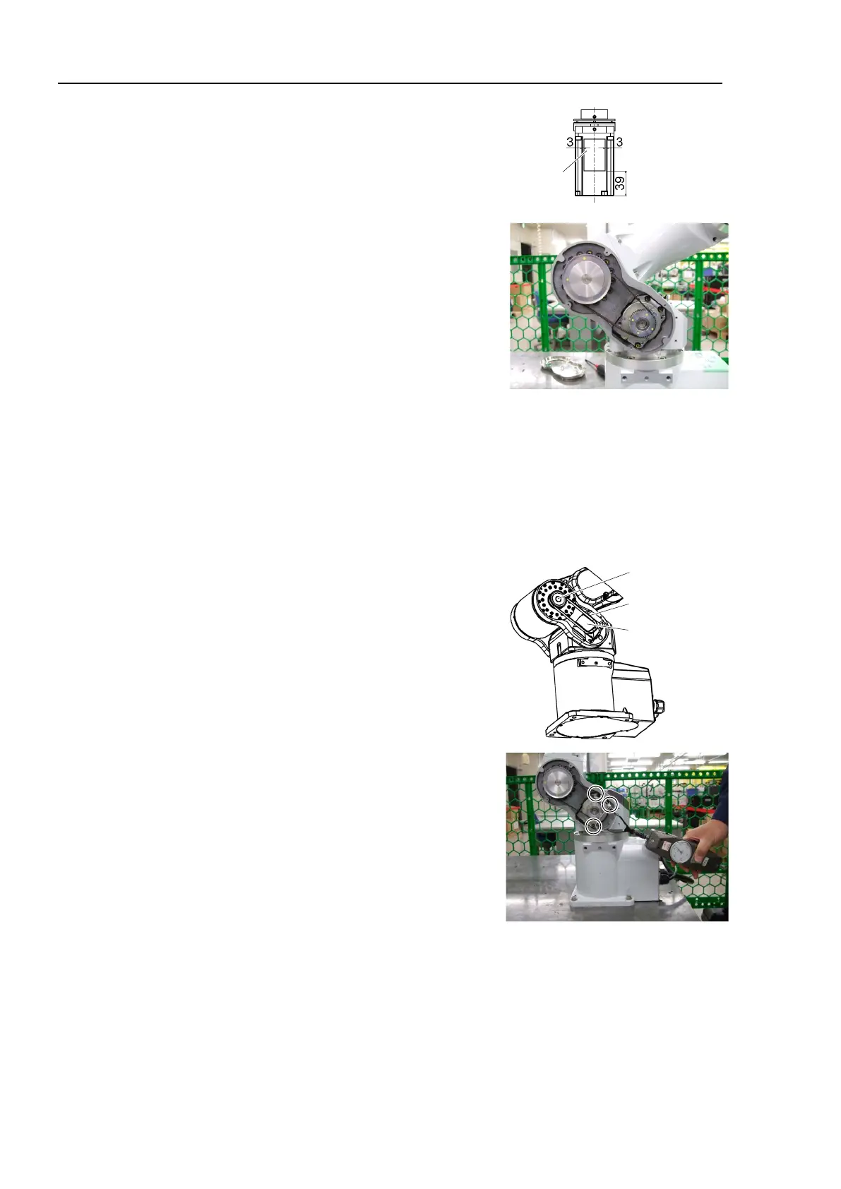
Place the timing belt around the pulley 1 and the pulley 2.
Check that the teeth of the timing belt engage with these of the
pulley.
When securing the motor unit temporarily, make sure that the
motor unit can be moved by hand, and it does not tilt when being
pulled. If the unit is secured too loose or too tight, the belt will
not have proper tension.
6. Apply tension to the Joint #2 motor unit and fix it.
Install the screw for tension adjustment to the motor plate.
Screw: M4×30 or longer (recommended length)
Pass a suitable cord or a string (insulation lock) to the screw. Pull the cord using a force gauge or a similar
tool to apply specified tension.
Joint #2 timing belt tension = 78.4 N ± 9.8 N (8 kgf ± 1 kgf)
Apply tension by pressing toward the “A” surface in the figure and
secure the motor unit.
Hexagon socket head cap bolt: 3-M4×18 (with a plain washer)
Tightening torque: 4.9 N·m (50 kgf·cm)
Make sure to remove the screw for tension adjustment.
7. Connect the following connectors.
Connectors: X121, X021, X62, BR021
8. Mount the Arm #1 cover and the Arm #1 side cover.
For details, refer to C4 Maintenance: 3. Covers.
9. Perform the calibration.
For details, refer to C4 Maintenance: 16. Calibration.