Safety 2. Part Names and Functions
RC700 / RC700-A Rev.23 15
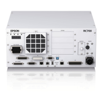
(6) Option slot
Option boards such as expansion I/O board, Fieldbus I/O board, RS-232C board, PG
board, Analog I/O board, and Force Sensor I/F board can be installed. Four slots are
available.
For details, refer to Setup & Operation 13.Option Slots.
(7) Battery
A lithium battery for data backup.
(8) POWER switch
Turns ON or OFF the Controller.
(9) Connection Check label
The details of
the Manipulator to be connected are recorded
on the label as shown in the right. The label indicates the
Manipulator model and Manipulator serial number.
(10) EMERGENCY connector
This connector is used for input/output from/to Emergency Stop and Safety Door
switches. For details, refer to the Setup & Operation 9. EMERGENCY.
(11) TP port
Connects Teach Pendant TP1, TP2, TP3 (Option) and TP bypass plug. Note that the
shape of the TP port differs between RC700 and RC700-A.
For details, refer to Setup & Operation 8. TP Port.
Do not connect the following to the TP port of RC700/RC700-A. It may result in
malfunction of the device since the pin assignments are different.
OPTIONAL DEVICE dummy plug
Operation Pendant OP500
Operator Pendant OP500RC
Jog Pad JP500
Teaching Pendant TP-3**
Operator Panel OP1
(12) Standard RS-232C port
This port is used for the RS-232C communication with external devices.
For details, refer to
Setup & Operation 10. Standard RS-232C Port.
(13) Encoder Voltage Adjustment Switch
Use this switch to adjust voltage according to length of M/C cable. (adjusted as a
factory default)
Wrong setting may result in Robot system malfunction.
(14) M/C SIGNAL connector
This connector is used for signals such as the manipulator’s motor position detector,
etc. Connect the Manipulator’s dedicated signal cable.

 Loading...