Safety 2. Part Names and Functions
16 RC700 / RC700-A Rev.23
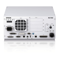
(15) R-I/O connector
This connector is for the input signals used for the real time I/O function.
(16) RC700: DU OUT connector / RC700-A: OUT connecter
The connector for Drive Unit.
(17) Development PC connection USB port
This port connects the Controller and the Development PC using a USB cable.
Do not connect other devices except the Development PC.
For details, refer to Setup & Operation 5. Development PC Connection USB Port.
(18) Memory port
This port connects the common USB memory for Controller backup function. Do
not connect other USB devices except the USB memory.
For details, refer to Setup & Operation 6. Memory Port.
(19) Trigger Switch
This switch is for Controller backup function using the USB memory.
For details, refer to Setup & Operation 6. Memory Port.
(20) LAN (Ethernet communication) port
This port connects the Controller and the Development PC using an Ethernet cable.
100BASE-TX / 10BASE-T communication are available.
For details, refer to Setup & Operation 7. LAN (Ethernet communication) Port.
(21) I/O connector
This connector is used for input/output device. There are 24 inputs and 16 outputs.
For details, refer to Setup & Operation 11. I/O Connector.
(22) AC IN
The connector for 200VAC power input.
For details, refer to Setup & Operation 3.3.2 AC Power Cable.
(23) Signature label
The serial number of the Controller and other information are shown.

 Loading...