Appendix A Assembly Instructions
A-2 ER1 User Guide
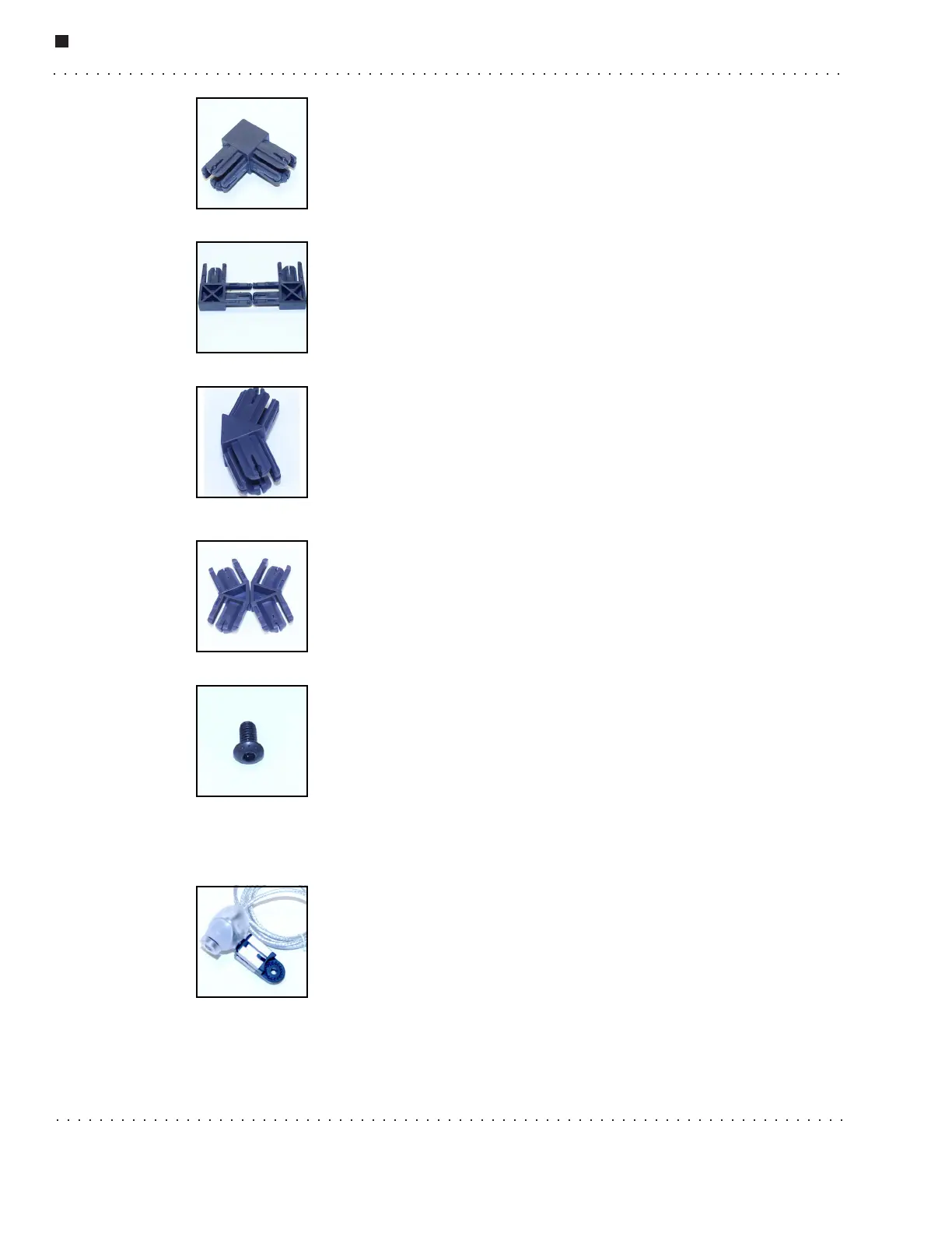
90
o
Connector
This connector is used to form the laptop cradle. Remember to use set
screws to tighten the connection.
The 90
o
connectors come as two halves that need to be pressed together
to form a whole unit before they are inserted into an aluminum beam.
There are four 90
o
connector halves in your kit.
135
o
Connector
The 135
o
connectors are used to attach the top of the robot to the bottom.
The 135
o
connectors come as halves. You must press the two halves
together before using the connector. There are four 135
o
connector halves
in your kit.
Allen Screw
The Allen screws are used for such things as attaching the motors and the
struts. There are two sizes of Allen screws used in the ER1: 3/8'' and
1/2''. Use the two larger Allen wrenches that come with your kit to
tighten the Allen screws. The Allen screws are already screwed into the
T-nuts. (See the T-Nuts section for more information.) All of the Allen
screws you will need are attached to the subassemblies, so you won’t find any of these
loose in the box.
Camera Assembly
The camera assembly is designed to be installed at the topmost part of
the robot. The robot uses the camera for object recognition, and to take
pictures and video. It provides the video feed for teleoperation, and can
be used for rudimentary obstacle avoidance. (For better obstacle
avoidance, a second camera (not included) is recommended.) There is
one camera assembly in your kit.