273
Special information
Additionally, the following memory is required depending on the Detector
configurations:
131 kilobytes if at least one balancing or run up/coast down configuration
exists on the Detector.
30 bytes for each unit used. As a rule 5-10 units are stored on the Detector.
54 bytes for each comment used.
Example: 500 CM configurations are sent to the Detector (500 * 572 bytes
= approx. 286 kB), leaving 2.7 MB - 0.286 MB = 2.414 MB for time signals
and free measurements. This means, that 2,414 MB / 16436 bytes (@
3200 lines) = 146 time signals can still be stored. The remaining memory
of about 14 kB can then be used for about 23 free CM measurements.
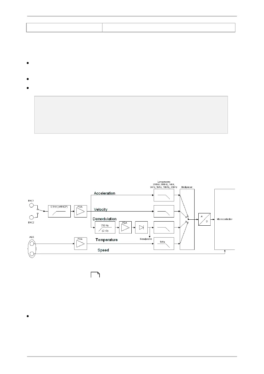
7.5 Analog branches in the Detector III
Depending on the selected characteristic value the sensor signals are
preconditioned by different signal paths in the Detector.
The measuring signal reaches the Detector via the sensor module (BNC1 or
BNC2, see "Connectors" ), where it passes a highpass filter (0.1 Hz) when the
sensors are active. The signal is then amplified in a PGA (
programmable gain amplifier
). After the amplifier the signal is subdivided into three branches, each of which
can have a different filter.
The acceleration and velocity branch both have their own lowpass filter with a
selectable corner frequency, so only the part of the signal below this frequency
can pass. In spite of its name, the acceleration is what is actually measured in
the velocity branch. This signal is integrated into the spectrum to calculate the
characteristic velocity values.
216