216
6.2 Connectors
The Detector has a total of 6 connectors on the top or shaft end:
Each connection accommodates one active sensor with excitation current (4.7
mA).
Port 1 is always used for CM measurements. Port 2 can be used for two-plane
balancing measurements.
Because the Detector is a single-channel device it cannot perform
measurements at both ports simultaneously!
Connection for headset or analog recording device. The headset connection can
only be activated via the "Single measurements" menu.
Connection for a serial data line to facilitate exchange of data with the computer
(RS 232 interface).
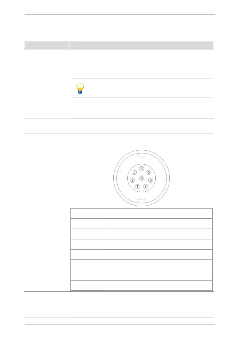
A temperature sensor or trigger sensor may be connected to the AUX socket. It
is assigned as follows:
12 V supply for trigger sensors (12 V against DGND)
GND Trigger sensor signal
5 V supply for trigger sensors (5 V against DGND)
Charging port
(4-pin socket next to
serial port)
For connection of battery charger.