4 System Composition
6
FOCUSED PHOTONICS INC
pressure) monitoring sub-system and data acquisition and processing sub-system. The following
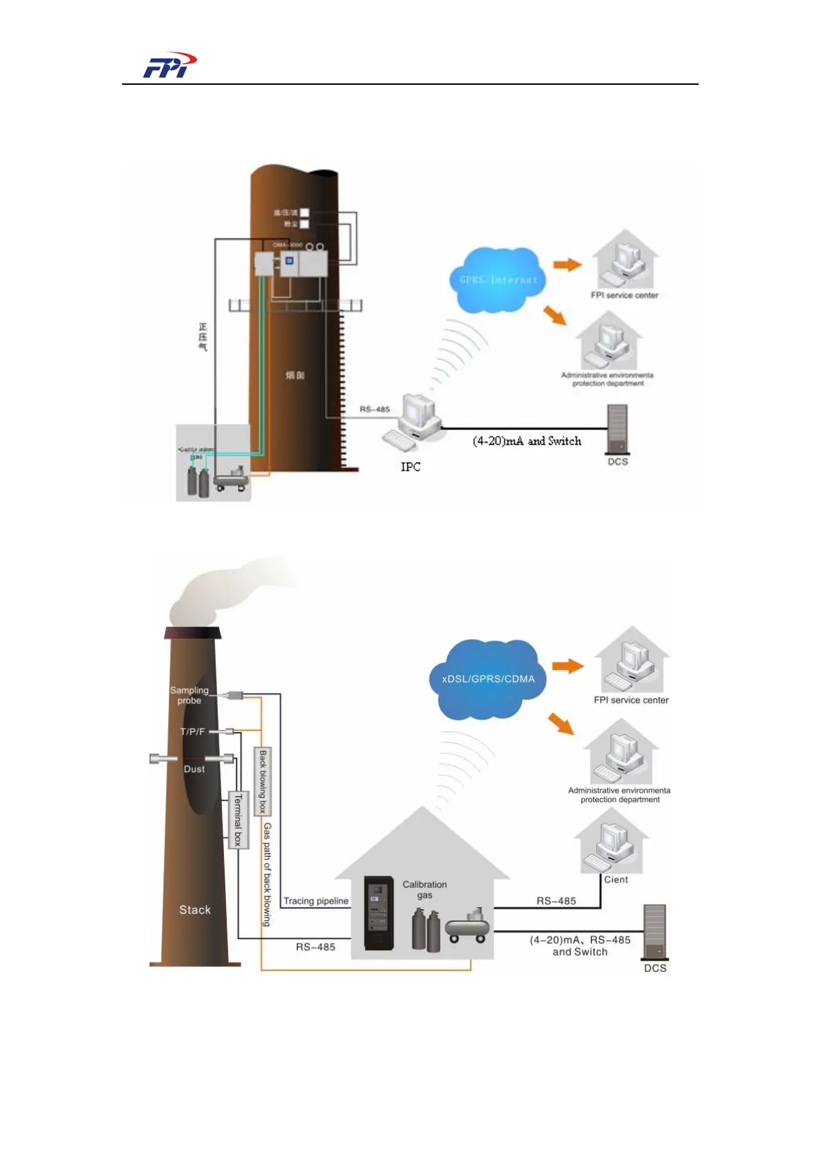
Fig 4-1 and Fig 4-2 show the difference of on-site mode and extraction mode.
Fig 4-1 CEMS-2000 System Architecture (Wall mounted)
Fig 4-2 CEMS-2000 System Architecture (Rack mounted)
As illustrated in the above figure, the gaseous pollutants monitoring sub-system is composed
of integrated sampling unit and OMA-2000 optical fiber spectrometer, measuring the density of