8-48 745 Transformer Management Relay GE Power Management
8.3 MODBUS MEMORY MAP 8 COMMUNICATIONS
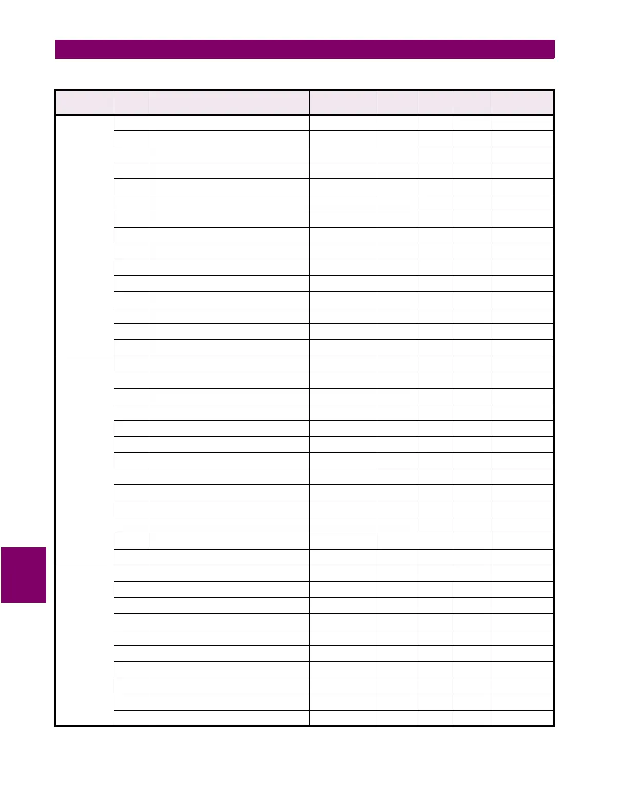
8
TIMERS
continued
1D92 Timer 7 Start --- --- --- F62 0 = End
1D93 Timer 7 Pickup Delay 0.00 to 600.00 0.01 s F3 0.00 s
1D94 Timer 7 Dropout Delay 0.00 to 600.00 0.01 s F3 0.00 s
1D95 Timer 8 Start --- --- --- F62 0 = End
1D96 Timer 8 Pickup Delay 0.00 to 600.00 0.01 s F3 0.00 s
1D97 Timer 8 Dropout Delay 0.00 to 600.00 0.01 s F3 0.00 s
1D98 Timer 9 Start --- --- --- F62 0 = End
1D99 Timer 9 Pickup Delay 0.00 to 600.00 0.01 s F3 0.00 s
1D9A Timer 9 Dropout Delay 0.00 to 600.00 0.01 s F3 0.00 s
1D9B Timer 10 Start --- --- --- F62 0 = End
1D9C Timer 10 Pickup Delay 0.00 to 600.00 0.01 s F3 0.00 s
1D9D Timer 10 Dropout Delay 0.00 to 600.00 0.01 s F3 0.00 s
1D9E Reserved
↓↓ ↓
↓↓↓ ↓
1DFF Reserved
FORCE
OUTPUT
RELAYS
1E00 Force Output Relays Function --- --- --- F30 0 = Disabled
1E01 Force Output Relay 1 --- --- --- F34
0 = De-energized
1E02 Force Output Relay 2 --- --- --- F34
0 = De-energized
1E03 Force Output Relay 3 --- --- --- F34
0 = De-energized
1E04 Force Output Relay 4 --- --- --- F34
0 = De-energized
1E05 Force Output Relay 5 --- --- --- F34
0 = De-energized
1E06 Force Output Relay 6 --- --- --- F34
0 = De-energized
1E07 Force Output Relay 7 --- --- --- F34
0 = De-energized
1E08 Force Output Relay 8 --- --- --- F34
0 = De-energized
1E09 Force Self-Test Relay --- --- --- F34
0 = De-energized
1E0A Reserved
↓↓ ↓
↓↓↓ ↓
1E0F Reserved
FORCE
ANALOG
OUTPUTS
1E10 Force Analog Outputs Function --- --- --- F30 0 = Disabled
1E11 Force Analog Output 1 0 to 100 1 % F1 0%
1E12 Force Analog Output 2 0 to 100 1 % F1 0%
1E13 Force Analog Output 3 0 to 100 1 % F1 0%
1E14 Force Analog Output 4 0 to 100 1 % F1 0%
1E15 Force Analog Output 5 0 to 100 1 % F1 0%
1E16 Force Analog Output 6 0 to 100 1 % F1 0%
1E17 Force Analog Output 7 0 to 100 1 % F1 0%
1E18 Reserved
↓↓ ↓
↓↓↓ ↓
Table 8–6: 745 MEMORY MAP (Sheet 32 of 57)
GROUP ADDR
(HEX)
DESCRIPTION RANGE STEP
VALUE
UNITS FORMAT
CODE
FACTORY
DEFAULT
 Loading...


