8-84 745 Transformer Management Relay GE Power Management
8.3 MODBUS MEMORY MAP 8 COMMUNICATIONS
8
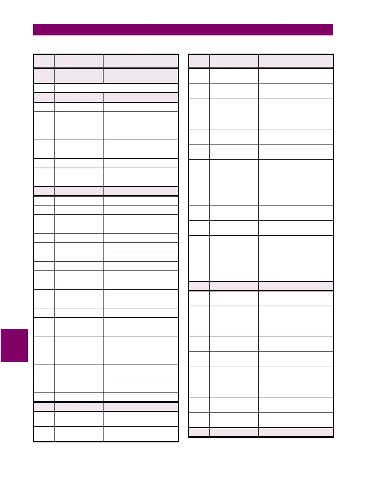
F53 16 bits UNSIGNED VALUE,
3 DECIMAL PLACES
Example: 1.234 stored as 1234
F54 16 bits FORCE LED STATE
xxxx xxxx 1111 1111 LED On/Off State (0 = Off, 1 = On)
xxxx xxxx xxxx xxx1 LED #1 (Top)
xxxx xxxx xxxx xx1x LED #2
xxxx xxxx xxxx x1xx LED #3
xxxx xxxx xxxx 1xxx LED #4
xxxx xxxx xxx1 xxxx LED #5
xxxx xxxx xx1x xxxx LED #6
xxxx xxxx x1xx xxxx LED #7
xxxx xxxx 1xxx xxxx LED #8 (Bottom)
F55 16 bits FRONT PANEL KEY
0000 0000 0000 0000 0 = '0'
0000 0000 0000 0001 1 = '1'
0000 0000 0000 0010 2 = '2'
0000 0000 0000 0011 3 = '3'
0000 0000 0000 0100 4 = '4'
0000 0000 0000 0101 5 = '5'
0000 0000 0000 0110 6 = '6'
0000 0000 0000 0111 7 = '7'
0000 0000 0000 1000 8 = '8'
0000 0000 0000 1001 9 = '9'
0000 0000 0000 1010 10 = '.'
0000 0000 0000 1011 11 = 'Value Up'
0000 0000 0000 1100 12 = 'Value Down'
0000 0000 0000 1101 13 = 'Message Up'
0000 0000 0000 1110 14 = 'Message Down'
0000 0000 0000 1111 15 = 'Next'
0000 0000 0001 0000 16 = 'Enter'
0000 0000 0001 0001 17 = 'Escape'
0000 0000 0001 0010 18 = 'Setpoints'
0000 0000 0001 0011 19 = 'Actual'
0000 0000 0001 0100 20 = 'Reset'
0000 0000 0001 0101 21 = 'Help'
F56 16 bits INPUT ASSERT FLAGS
xxxx xxxx xxxx xxx1 Input 1
(0 = Not Asserted, 1 = Asserted)
xxxx xxxx xxxx xx1x Input 2
(0 = Not Asserted, 1 = Asserted)
Table 8–7: 745 DATA FORMATS (Sheet 21 of 35)
FORMAT
CODE
APPLICABLE BITS DEFINITION
xxxx xxxx xxxx x1xx Input 3
(0 = Not Asserted, 1 = Asserted)
xxxx xxxx xxxx 1xxx Input 4
(0 = Not Asserted, 1 = Asserted)
xxxx xxxx xxx1 xxxx Input 5
(0 = Not Asserted, 1 = Asserted)
xxxx xxxx xx1x xxxx Input 6
(0 = Not Asserted, 1 = Asserted)
xxxx xxxx x1xx xxxx Input 7
(0 = Not Asserted, 1 = Asserted)
xxxx xxxx 1xxx xxxx Input 8
(0 = Not Asserted, 1 = Asserted)
xxxx xxx1 xxxx xxxx Input 9
(0 = Not Asserted, 1 = Asserted)
xxxx xx1x xxxx xxxx Input 10
(0 = Not Asserted, 1 = Asserted)
xxxx x1xx xxxx xxxx Input 11
(0 = Not Asserted, 1 = Asserted)
xxxx 1xxx xxxx xxxx Input 12
(0 = Not Asserted, 1 = Asserted)
xxx1 xxxx xxxx xxxx Input 13
(0 = Not Asserted, 1 = Asserted)
xx1x xxxx xxxx xxxx Input 14
(0 = Not Asserted, 1 = Asserted)
x1xx xxxx xxxx xxxx Input 15 (0 = Not Asserted, 1 =
Asserted)
1xxx xxxx xxxx xxxx Input 16 (0 = Not Asserted, 1 =
Asserted)
F57 16 bits OUTPUT RELAY OPERATE FLAGS
xxxx xxxx xxxx xxx1 Output Relay 1
(0 = Not Operated, 1 = Operated)
xxxx xxxx xxxx xx1x Output Relay 2
(0 = Not Operated, 1 = Operated)
xxxx xxxx xxxx x1xx Output Relay 3
(0 = Not Operated, 1 = Operated)
xxxx xxxx xxxx 1xxx Output Relay 4
(0 = Not Operated, 1 = Operated)
xxxx xxxx xxx1 xxxx Output Relay 5
(0 = Not Operated, 1 = Operated)
xxxx xxxx xx1x xxxx Output Relay 6
(0 = Not Operated, 1 = Operated)
xxxx xxxx x1xx xxxx Output Relay 7
(0 = Not Operated, 1 = Operated)
xxxx xxxx 1xxx xxxx Output Relay 8
(0 = Not Operated, 1 = Operated)
xxxx xxx1 xxxx xxxx Self-Test Relay
(0 = Not Operated, 1 = Operated)
F58 16 bits DEMAND METER TYPE
Table 8–7: 745 DATA FORMATS (Sheet 22 of 35)
FORMAT
CODE
APPLICABLE BITS DEFINITION
 Loading...


