GE Power Management 745 Transformer Management Relay 8-85
8 COMMUNICATIONS 8.3 MODBUS MEMORY MAP
8
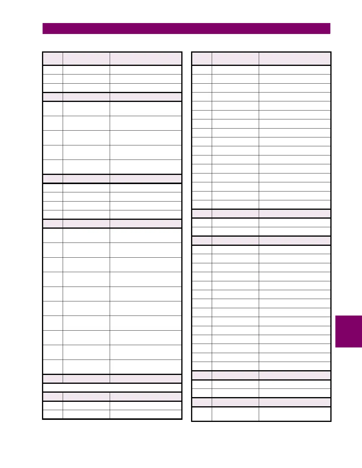
0000 0000 0000 0000 0 = Thermal
0000 0000 0000 0001 1 = Block Interval
0000 0000 0000 0010 2 = Rolling Demand
F59 16 bits
VIRTUAL OUTPUT OPERATE FLAGS
xxxx xxxx xxxx xxx1 Virtual Output 1
(0 = Not Operated, 1 = Operated)
xxxx xxxx xxxx xx1x Virtual Output 2
(0 = Not Operated, 1 = Operated)
xxxx xxxx xxxx x1xx Virtual Output 3
(0 = Not Operated, 1 = Operated)
xxxx xxxx xxxx 1xxx Virtual Output 4
(0 = Not Operated, 1 = Operated)
xxxx xxxx xxx1 xxxx Virtual Output 5
(0 = Not Operated, 1 = Operated)
F60 16 bits ACTIVE SETPOINT GROUP
0000 0000 0000 0000 0 = Group 1
0000 0000 0000 0001 1 = Group 2
0000 0000 0000 0010 2 = Group 3
0000 0000 0000 0011 3 = Group 4
F61 16 bits TIMER OPERATE FLAGS
xxxx xxxx xxxx xxx1 Timer 1
(0 = Not Operated, 1 = Operated)
xxxx xxxx xxxx xx1x Timer 2
(0 = Not Operated, 1 = Operated)
xxxx xxxx xxxx x1xx Timer 3
(0 = Not Operated, 1 = Operated)
xxxx xxxx xxxx 1xxx Timer 4
(0 = Not Operated, 1 = Operated)
xxxx xxxx xxx1 xxxx Timer 5
(0 = Not Operated, 1 = Operated)
xxxx xxxx xx1x xxxx Timer 6
(0 = Not Operated, 1 = Operated)
xxxx xxxx x1xx xxxx Timer 7
(0 = Not Operated, 1 = Operated)
xxxx xxxx 1xxx xxxx Timer 8
(0 = Not Operated, 1 = Operated)
xxxx xxx1 xxxx xxxx Timer 9
(0 = Not Operated, 1 = Operated)
xxxx xx1x xxxx xxxx Timer 10
(0 = Not Operated, 1 = Operated)
F62 16 bits
FLEXLOGIC EQUATION (NO GATES)
Format F47 for tokens 0000 01111 and greater - i.e. no gates)
F63 16 bits VOLTAGE INPUT PARAMETERS
0000 0000 0000 0000 0 = W1 Van
0000 0000 0000 0001 1 = W1 Vbn
Table 8–7: 745 DATA FORMATS (Sheet 23 of 35)
FORMAT
CODE
APPLICABLE BITS DEFINITION
0000 0000 0000 0010 2 = W1 Vcn
0000 0000 0000 0011 3 = W1 Vab
0000 0000 0000 0100 4 = W1 Vbc
0000 0000 0000 0101 5 = W1 Vca
0000 0000 0000 0110 6 = W2 Van
0000 0000 0000 0111 7 = W2 Vbn
0000 0000 0000 1000 8 = W2 Vcn
0000 0000 0000 1001 9 = W2 Vab
0000 0000 0000 1010 10 = W2 Vbc
0000 0000 0000 1011 11 = W2 Vca
0000 0000 0000 1100 12 = W3 Van
0000 0000 0000 1101 13 = W3 Vbn
0000 0000 0000 1110 14 = W3 Vcn
0000 0000 0000 1111 15 = W3 Vab
0000 0000 0001 0000 16 = W3 Vbc
0000 0000 0001 0001 17 = W3 Vca
F64 16 bits HARMONIC PARAMETERS
0000 0000 0000 0000 0 = 2nd
0000 0000 0000 0001 1 = 2nd+5th
F65 16 bits TRACE MEMORY CHANNEL
0000 0000 0000 0000 0 = W1 Ia
0000 0000 0000 0001 1 = W1 Ib
0000 0000 0000 0010 2 = W1 Ic
0000 0000 0000 0011 3 = W2 Ia
0000 0000 0000 0100 4 = W2 Ib
0000 0000 0000 0101 5 = W2 Ic
0000 0000 0000 0110 6 = W3 Ia
0000 0000 0000 0111 7 = W3 Ib
0000 0000 0000 1000 8 = W3 Ic
0000 0000 0000 1001 9 = W1/2 Ig
0000 0000 0000 1010 10 = W2/3 Ig
0000 0000 0000 1011 11 = Voltage
0000 0000 0000 1100 12 = Logic Inputs
0000 0000 0000 1101 13 = Output Relays
F66 16 bits OUTPUT OPERATION
0000 0000 0000 0000 0 = Self-resetting
0000 0000 0000 0001 1 = Latched
F67 16 bits BLOCK OPERATION OF OUTPUTS
xxxx xxxx xxxx xxx1 Output Relay 1 (0 = Allow
Operation, 1 = Block Operation)
Table 8–7: 745 DATA FORMATS (Sheet 24 of 35)
FORMAT
CODE
APPLICABLE BITS DEFINITION
 Loading...


