8-86 745 Transformer Management Relay GE Power Management
8.3 MODBUS MEMORY MAP 8 COMMUNICATIONS
8
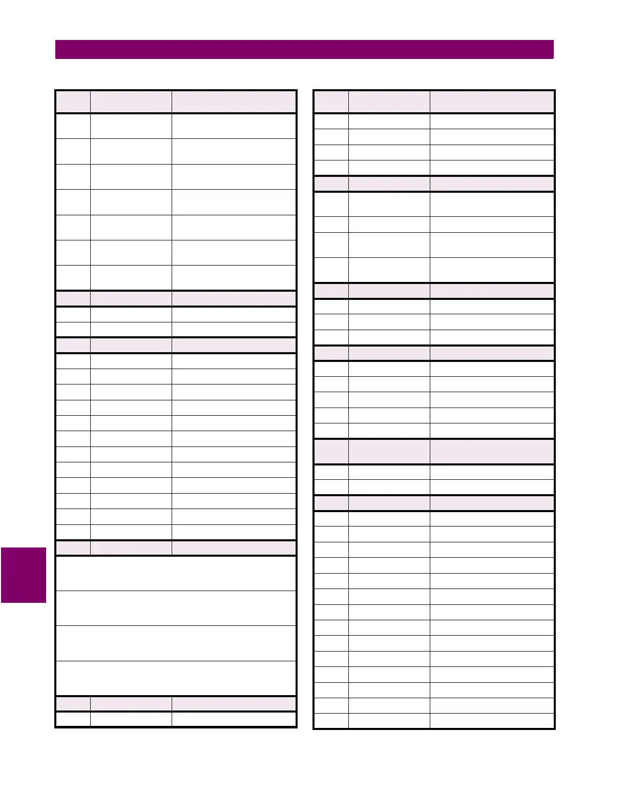
xxxx xxxx xxxx xx1x Output Relay 2 (0 = Allow
Operation, 1 = Block Operation)
xxxx xxxx xxxx x1xx Output Relay 3 (0 = Allow
Operation, 1 = Block Operation)
xxxx xxxx xxxx 1xxx Output Relay 4 (0 = Allow
Operation, 1 = Block Operation)
xxxx xxxx xxx1 xxxx Output Relay 5 (0 = Allow
Operation, 1 = Block Operation)
xxxx xxxx xx1x xxxx Output Relay 6 (0 = Allow
Operation, 1 = Block Operation)
xxxx xxxx x1xx xxxx Output Relay 7 (0 = Allow
Operation, 1 = Block Operation)
xxxx xxxx 1xxx xxxx Output Relay 8 (0 = Allow
Operation, 1 = Block Operation)
F68 16 bits RESET TIME
0000 0000 0000 0000 0 = Instantaneous
0000 0000 0000 0001 1 = Linear
F69 16 bits PLAYBACK MEMORY CHANNEL
0000 0000 0000 0000 0 = W1 Ia
0000 0000 0000 0001 1 = W1 Ib
0000 0000 0000 0010 2 = W1 Ic
0000 0000 0000 0011 3 = W2 Ia
0000 0000 0000 0100 4 = W2 Ib
0000 0000 0000 0101 5 = W2 Ic
0000 0000 0000 0110 6 = W3 Ia
0000 0000 0000 0111 7 = W3 Ib
0000 0000 0000 1000 8 = W3 Ic
0000 0000 0000 1001 9 = W1/2 Ig
0000 0000 0000 1010 10 = W2/3 Ig
0000 0000 0000 1011 11 = Voltage
F70 16 bits TRACE/PLAYBACK MEMORY DATA
Trace/Playback Channel Selector Index = 0 – 10 (i.e. any current input)
2'S COMPLEMENT SIGNED VALUE
Examples: 1.000 x CT stored as 500; -0.500 x CT stored as -250
Trace/Playback Channel Selector Index = 11 (i.e. Voltage)
2'S COMPLEMENT SIGNED VALUE
Examples: 1.000 x VT stored as 1000; -0.500 x VT stored as -500
Trace Channel Selector Index = 12 (i.e. Logic Inputs)
AS PER FORMAT F49
Example: "Logic Inputs 1 and 3 closed" stored as 0005 hex
Trace Channel Selector Index = 13 (i.e. Output Relays)
AS PER FORMAT F50
Example: "Output Relays 2 and 4 energized" stored as 000A hex
F71 16 bits FACTORY SERVICE COMMANDS
0000 0000 0000 0000 0 = Clear Any Pending Commands
Table 8–7: 745 DATA FORMATS (Sheet 25 of 35)
FORMAT
CODE
APPLICABLE BITS DEFINITION
0000 0000 0000 0001 1 = Load Factory Default Setpoints
0000 0000 0000 0010 2 = Load Default Calibration Data
0000 0000 0000 0011 3 = Clear Diagnostic Data
0000 0000 0000 0100 4 = Clear RMS Min/Max Data
F72 16 bits FORCE OTHER HARDWARE
xxxx xxxx xxxx xxx1 LEDs (0=Normal, 1= Use LED
force codes)
xxxx xxxx xxxx xx1x Beeper (0=Normal, 1= On)
xxxx xxxx xxxx x1xx External Watchdog
(0=Normal, 1=Stop Updating)
xxxx xxxx xxxx 1xxx Internal Watchdog
(0=Normal, 1=Stop Updating)
F73 16 bits PARITY
0000 0000 0000 0000 0 = None
0000 0000 0000 0001 1 = Odd
0000 0000 0000 0010 2 = Even
F74 16 bits EDIT SETPOINT GROUP
0000 0000 0000 0000 0 = Group 1
0000 0000 0000 0001 1 = Group 2
0000 0000 0000 0010 2 = Group 3
0000 0000 0000 0011 3 = Group 4
0000 0000 0000 0100 4 = Active Group
F75 16 bits VIRTUAL INPUT PROGRAMMED
STATE
0000 0000 0000 0000 0 = Open
0000 0000 0000 0001 1 = Closed
F76 16 bits FLEXLOGIC EQUATION ERROR
0000 0000 0000 0000 0 = None
0000 0000 0000 0001 1 = Output Relay 1
0000 0000 0000 0010 2 = Output Relay 2
0000 0000 0000 0011 3 = Output Relay 3
0000 0000 0000 0100 4 = Output Relay 4
0000 0000 0000 0101 5 = Output Relay 5
0000 0000 0000 0110 6 = Output Relay 6
0000 0000 0000 0111 7 = Output Relay 7
0000 0000 0000 1000 8 = Output Relay 8
0000 0000 0000 1001 9 = Trace Memory Trigger
0000 0000 0000 1010 10 = Virtual Output 1
0000 0000 0000 1011 11 = Virtual Output 2
0000 0000 0000 1100 12 = Virtual Output 3
0000 0000 0000 1101 13 = Virtual Output 4
Table 8–7: 745 DATA FORMATS (Sheet 26 of 35)
FORMAT
CODE
APPLICABLE BITS DEFINITION

 Loading...


