11-2 745 Transformer Management Relay GE Power Management
11.1 COMMISSIONING SUMMARY 11 SETPOINT TABLES
11
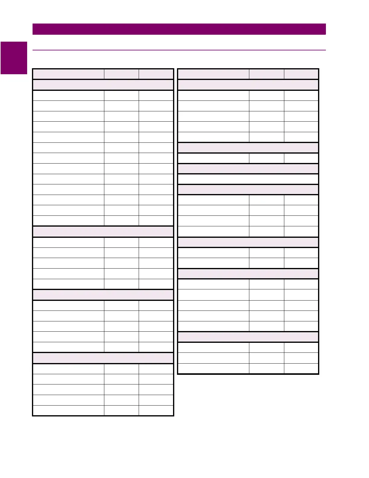
11.1.2 S2 SYSTEM SETUP
Table 11–2: S2 SYSTEM SETUP(Sheet 1 of 2)
DESCRIPTION DEFAULT USER VALUE DESCRIPTION DEFAULT USER VALUE
TRANSFORMER ONLOAD TAP CHANGER
Nominal Frequency 60 Hz Winding With Tap Changer None
Frequency Tracking Enabled Number of Tap Positions 33
Phase Sequence ABC Min. Tap Position Voltage (kV) 61.0
Transformer Type Y/d30° Voltage Increment Per Tap (kV) 0.50
Load Loss at Rated Load 1250 kW Res. Increment Per Tap (W) 33
Low Voltage Winding Rating Above 5 kV
HARMONIC DERATING
Rated Winding Temp Rise 65°C (oil) Estimation Disabled
No-Load Loss (KW) 125.0 kW
FLEXCURVES
Type of Cooling OA see Table 11–3: FLEXCURVES TABLE on page 11–4
Rated Top Oil Rise Over Ambient
10°C
VOLTAGE INPUT
XFMR THRML capacity 1.00 kWh/°C Voltage Sensing Disabled
Winding Time Constant 2.00 min. Voltage Input Parameter W1 Van
Set Accumulated Loss of Life
0 x 10 h Nominal VT Secondary Voltage 120.0 V
WINDING 1
VT Ratio 1000:1
Nom. Voltage 220.0 kV
AMBIENT TEMPERATURE
Rated Load 100.0 MVA Ambient Temperature Sensing Disabled
Phase CT Primary 500 A Ambient RTD Type 100 W Pl.
Ground CT Primary 500 A
ANALOG INPUT
Series 3
∅
Resistance 10.700 W Analog Input Name
ANALOG INPUT
WINDING 2
Analog Input Units "uA"
Nom. Voltage 69.0 V Analog Input Range 0-1 mA
Rated Load 100.0 MVA Analog Input Minimum Value 0 <Units>
Phase CT Primary 1500 A Analog Input Maximum Value 1000
<Units>
Ground CT Primary 1500 A
DEMAND METERING
Series 3
∅
Resistance 2.100 W Current Demand Meter Type Thermal
WINDING 3
Thermal 90% Response Time 15 min.
Nom. Voltage 69.0 kV Time Interval 20 min.
Rated Load 100.0 MVA
Phase CT Primary 1500 A
Ground CT Primary 1500 A
Series 3
∅
Resistance 2.100 W

 Loading...


