REV 5 DIRECTION 2173225-100
7-7
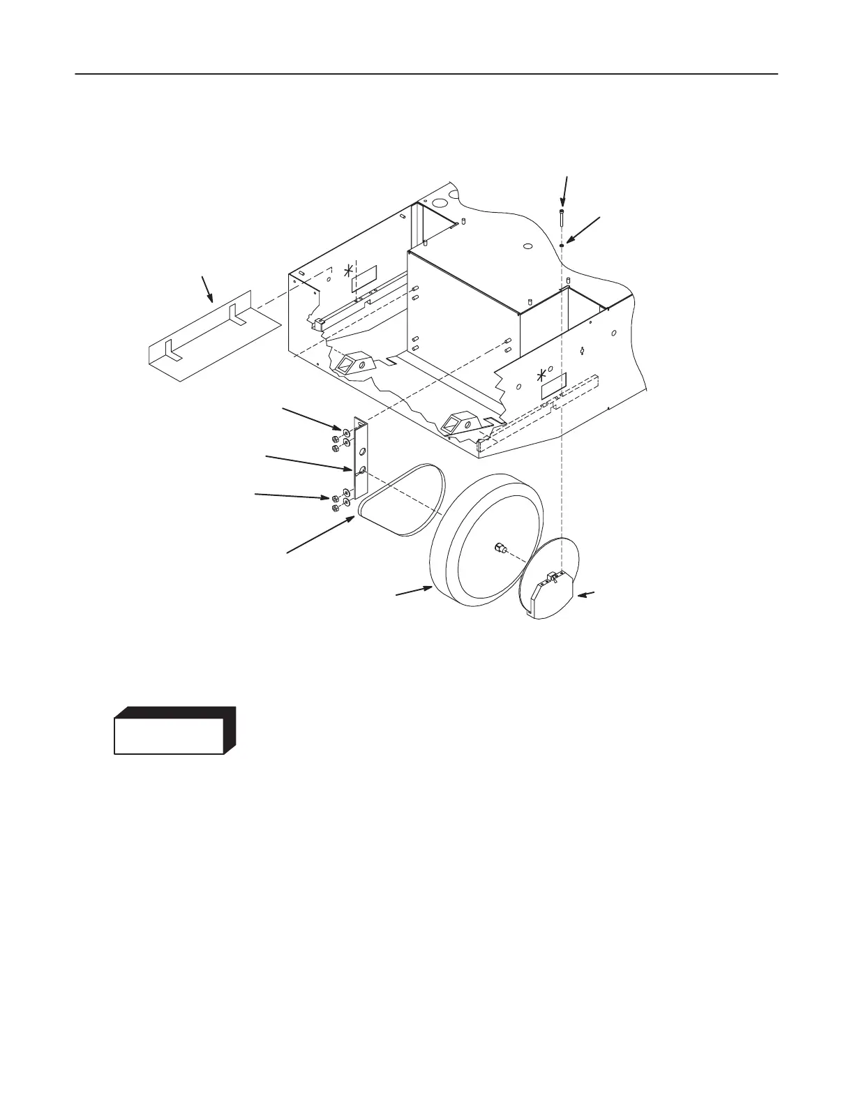
ILLUSTRATION 7-7
SPLASH
GUARD
HEAD CAP SCREW
WASHER
DRIVE
WHEEL
SUPPORT
ANGLE
FLAT WASHER
HEX HEAD
LOCKNUT
DRIVE BELT
RIGHT SIDE AXLE
DISC/CALIPER
ASSEMBLY
* $'(## &") ! #'
%( This procedure covers the installation of either the right or left drive wheel.
%( Apply light coat of grease (Lubriplate Fiske 630-A-A) to each end of axle.
1. The unit is on blocks approximately 10 inches (25 cm) above the floor.
2. Place the caliper assembly on the wheel axle.
3. Install the drive belt on the drive wheel pulley.
4. Lift the drive wheel through the bottom of the base assembly and into position
in the notch in the bottom of the wheel mounting support. See Illustration 7-7.
5. Attach the wheel and caliper assembly to the wheel mounting support with four
hex socket head capscrews. Do not tighten in place.

 Loading...


