REV 5 DIRECTION 2173225-100
10-11
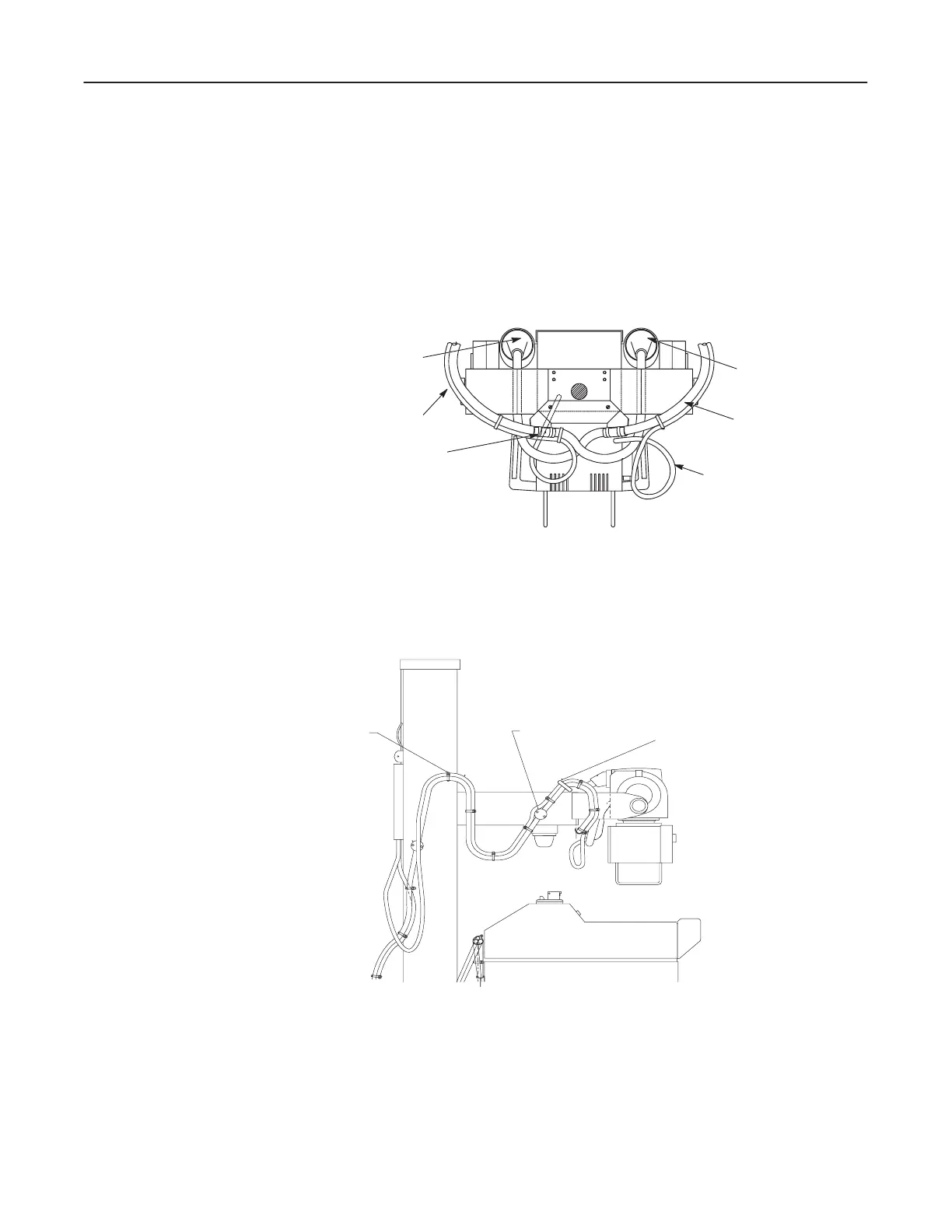
Stator Cable
1. The stator cable starts at the tube, passes under the cathode cable and joins the
anode cable just before clamp L." There is a large loop of cable before reaching
clamp point L." The cables are ty-rapped on each side of clamp point L" as
shown in Illustration 10-13.
ILLUSTRATION 10-13
COLLIMATOR CABLE
ANODE
CLAMP POINT L"
CATHODE
CATHODE
STATOR CABLE
2. The stator cable follows the anode cable from clamp point L" to strap point M"
with two ty-raps in between. See Illustration 10-14.
ILLUSTRATION 10-14
STRAP POINT G
STRAP POINT M
CLAMP POINT H

 Loading...


