4-11
Disconnect Brake
1. Remove the vertical column. Refer to Section 4-1.
2. Tag either the main or safety cable.
D This will eliminate confusion when securing them in their correct positions
on the carriage mounting strut.
3. Detach the main and safety cables form the carriage cable mounting strut. Refer
to Section 4-3.
4. Remove two screws in the bottom of terminal box located on back of vertical colĆ
umn and lift off cover.
5. Disconnect upper brake cable leads from terminal block. (It is important to tag
and record terminal points, otherwise there is a possibility of blowing internal
diode in brake if leads are improperly installed.)
6. Remove brake cable from terminal box and channel on back of column.
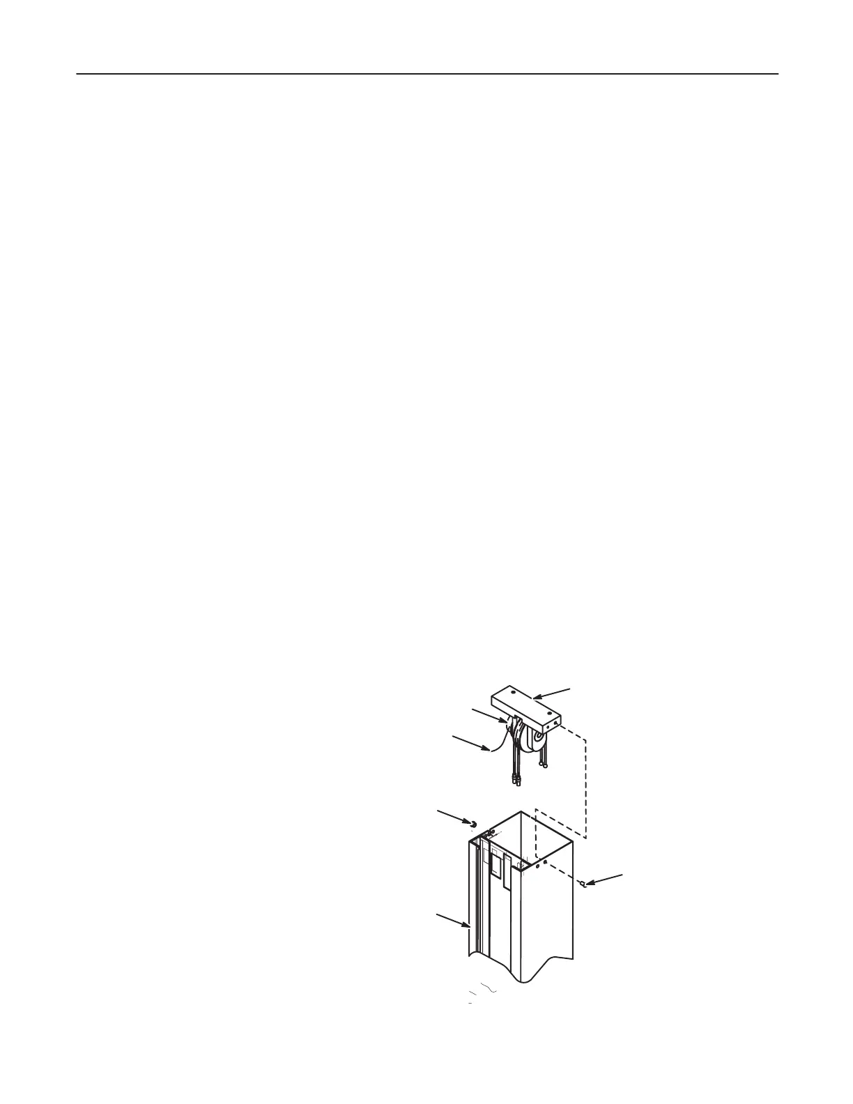
Remove Upper Pulley and Brake
7. Remove capscrews securing pulley and brake assembly to top of column. See IlĆ
lustration 4-6.
8. Remove Heyco bushing from column where brake cable enters pulley and brake
assembly. Bushing extends into pulley and brake casting.
ILLUSTRATION 4-6