3-12
1. Remove horizontal arm brake and cable assembly. Refer to Section 3-7.
2. Remove cable clip from bar support assembly by removing one machine screw.
See Illustration 3-7.
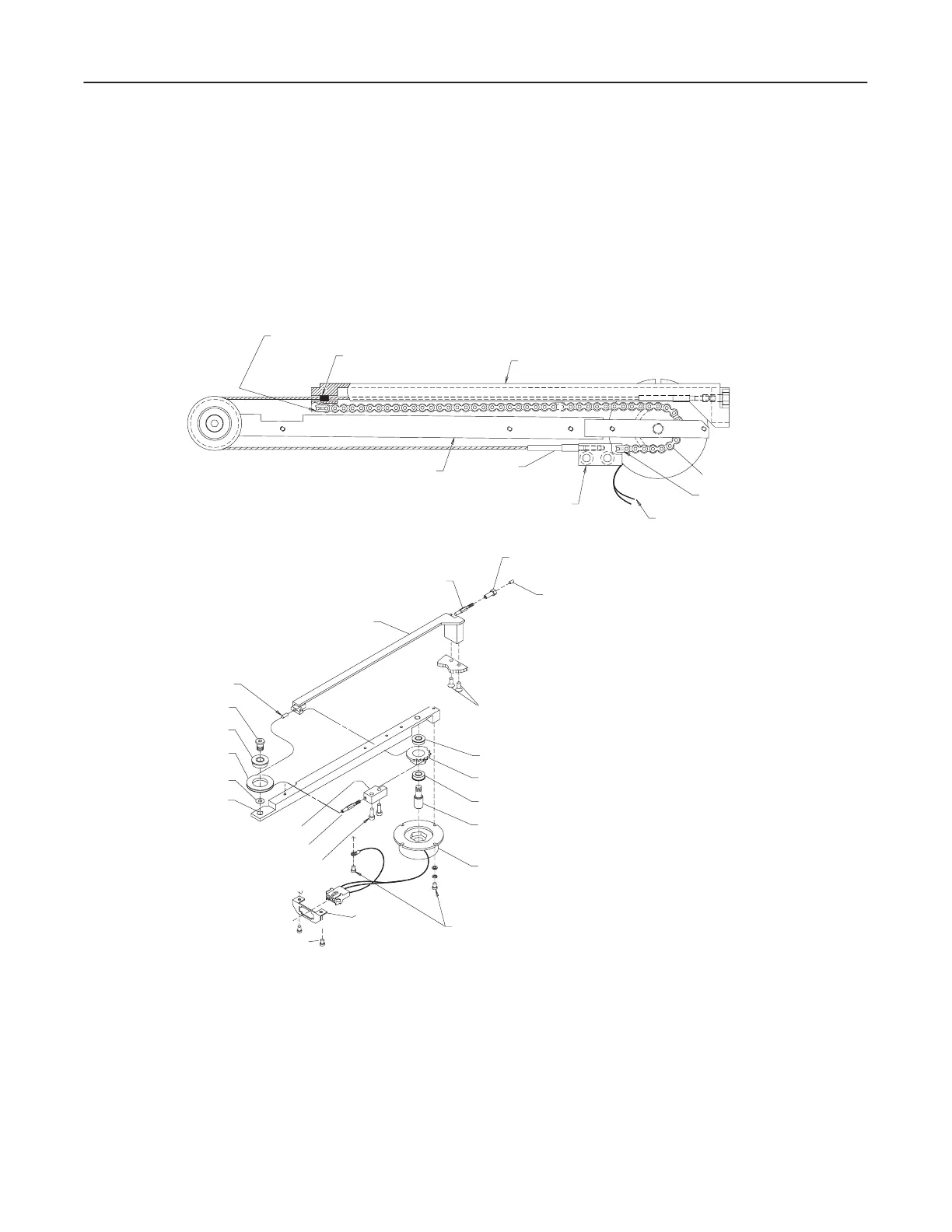
ILLUSTRATION 3-7
BRACKET
PULLEY SHAFT
PULLEY CABLE
CABLE BAR
PULLEY CABLE
CABLE ANCHOR
6–40 1/8 INCH SCREW
10–32X1/2 INCH SCREW
BEARING
SPROCKET
BEARING
CHAIN SHAFT
BRAKE
6–32X5/8 INCH SCREW
10–32X1 INCH SCREW
10–32X5/8 INCH SCREW
MOUNTING BLOCK
PULLEY CABLE
PULLEY BAR
WASHER
PULLEY
BEARING
MASTER LINK
MOUNTING BLOCK
CABLE BAR
BRAKE CHAIN
BRAKE CABLE
MASTER LINK
BRAKE WIRING
CABLE BAR
PULLEY BAR
3. Remove anchor nut from brake cable by turning counterclockwise. This nut has
been secured with set screws and Loctite.
4. Remove cable anchor end from bar support.
5. Slide ball end of cable from slot in cable bracket and remove from path around
pulley end on mounting plate.
6. Remove the brake cable from brake and cable assembly.