REV 5 DIRECTION 2173225-100
6-10
5 )./'' //!-4 *(+-/(!)/ *1!-
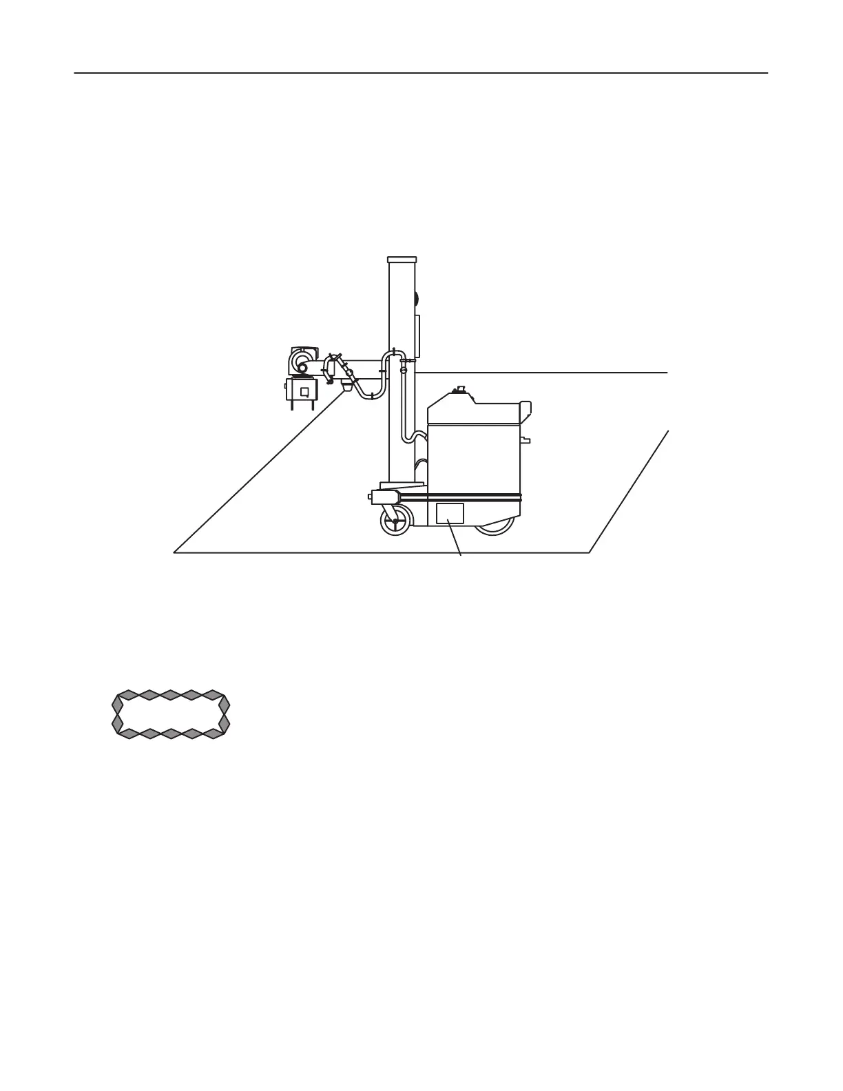
1. Place the unit on a level floor. Extend the horizontal arm and rotate it to the front
end of the AMX (vertical-column end). See Illustration 6-5.
ILLUSTRATION 6-5
ARM EXTENDED
LEVEL FLOOR
BOLTS TORQUED TO
75 IN. LBS. (8.4 N-m)
*/! Distribution of weight is necessary to install the battery compartment cover.
2. Place the remaining Insulator #1 in the compartment opening with cup-shaped
bumps pointing away from you.
$! //!-4 *(+-/(!)/ *1!- %. ) %)/!#-' +-/ *" /$! .! ..!('4 ''
.%3 *'/. (0./ ! %) +'! ) /*-,0! /* +*0) %)$!. !2/*)(!/5
!-. *- /$! .! ..!('4 ) ! 2-+! *- -&!
3. Install battery compartment cover as shown in Illustration 6-5.
4. Remove tape from free ends of all ground cables and connect to ground stud usĆ
ing flat washer and nut.

 Loading...


