EasyManuals Logo

GE AMX 4+ Technical Manual

GE AMX 4+
132 pages
To Next Page IconTo Next Page
To Previous Page IconTo Previous Page
Page #129 background imageLoading...
Page #129 background image
 
        
  
10-13
2. The cable continues from near clamp point H" and is ty-rapped to the anode
and stator cables at the locations shown in Illustration 10-16 until reaching strap
point G".
3. There is a large loop after strap point G" before the cable enters the bottom of
the vertical column assembly terminal box and is connected to the terminal strip
AMX3 A1 TS1. See Illustration 10-12 and Table 10-1.
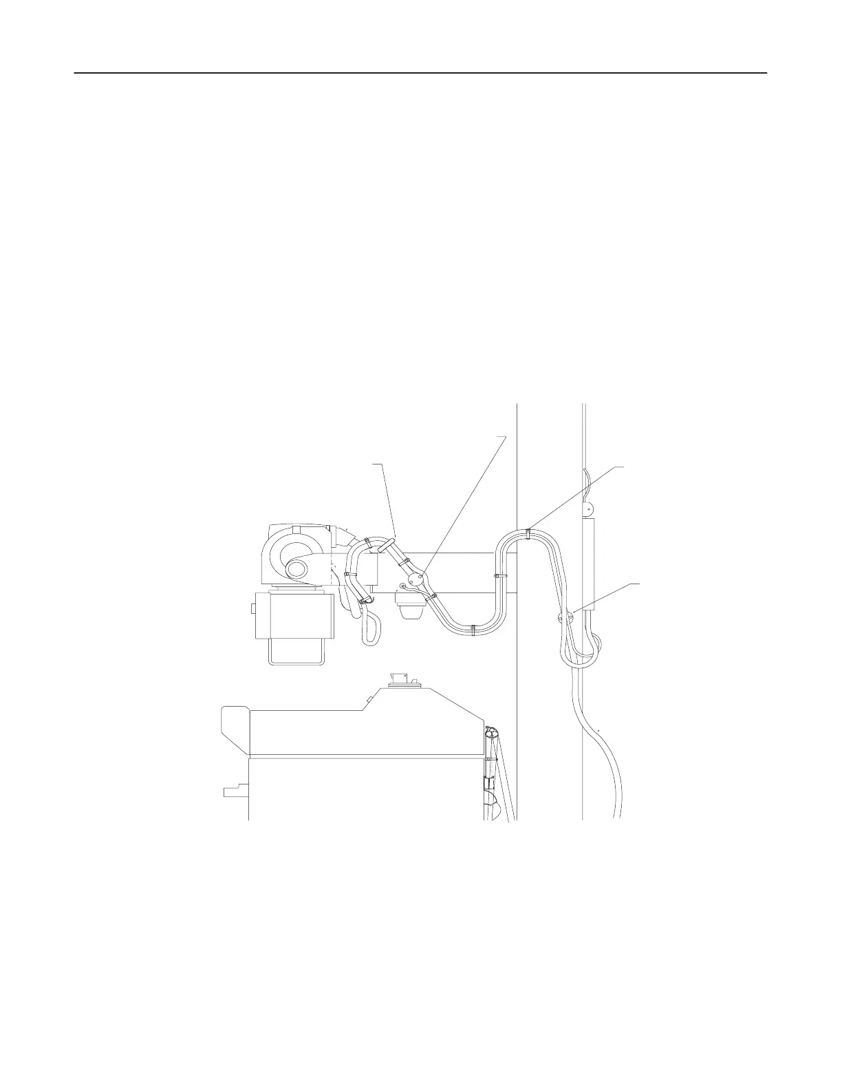
 Control Cable
The control cable exits the bottom of the terminal box on the rear of the vertical colĆ
umn assembly, passes beneath the anode cable and connects directly into the unit just
below the anode and cathode cables. The cable is loosely draped to accommodate arm
and column movements. See Illustration 10-17.
ILLUSTRATION 10-17
  
CLAMP POINT A
CLAMP POINT D
STRAP POINT N
 

Table of Contents

Other manuals for GE AMX 4+

Questions and Answers:

Question and Answer IconNeed help?

Do you have a question about the GE AMX 4+ and is the answer not in the manual?

GE AMX 4+ Specifications

General IconGeneral
TypeMobile X-ray System
Maximum kVp125 kVp
CollimatorManual Collimator
BatteryRechargeable, lead-acid
Image Receptor CompatibilityCR and DR systems
Focal Spot Size1.2 mm
mAs Range0.04 - 320 mAs
X-ray TubeRotating Anode

Related product manuals