REV 5 DIRECTION 2173225-100
1-6
$ " #!" "
The x-ray field and light field must be properly aligned to meet HHS requirements.
Two methods for accomplishing this are given below.
Method 1, Section 1-4-1, is only used if the Light Field to X-Ray Field Test PatĆ
tern," 46-198466P1, from an HHS Field Test Kit, 46-177372G1, is available.
Method 2, Section 1-4-2, uses lead strips to indicate the light field areas.
$$ Adjustment Method 1
1. Place loaded cassette (14 17 inches suggested) on floor directly beneath colliĆ
mator.
2. Adjust the collimator so that it is parallel to the cassette.
3. Set SID to 40 inches.
4. Place light field to x-ray field test pattern on top of cassette.
5. Turn on field lamp.
6. Adjust collimator blades so light field exactly covers the 8 10 inch (20.32 x 25.4
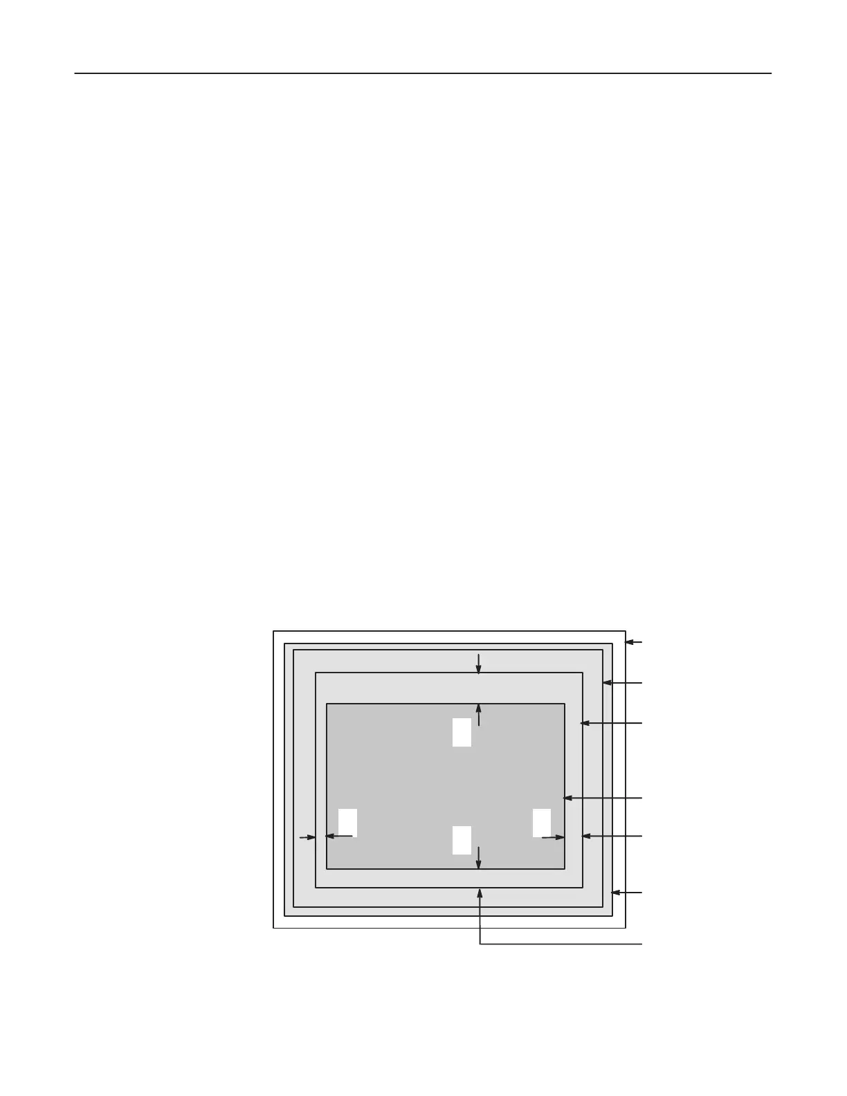
cm) rectangle on the test pattern. See Illustration 1-5.
ILLUSTRATION 1-5
C
D
AB
FILM
TEST PATTERN
8 X 10 INCH TEST
RECTANGLE
(LIGHT FIELD)
X-RAY FIELD
HORIZONTAL
DIFFERENCE
SECOND
EXPOSURE
VERTICAL
DIFFERENCE

 Loading...


