REV 5 DIRECTION 2173225-100
10-8
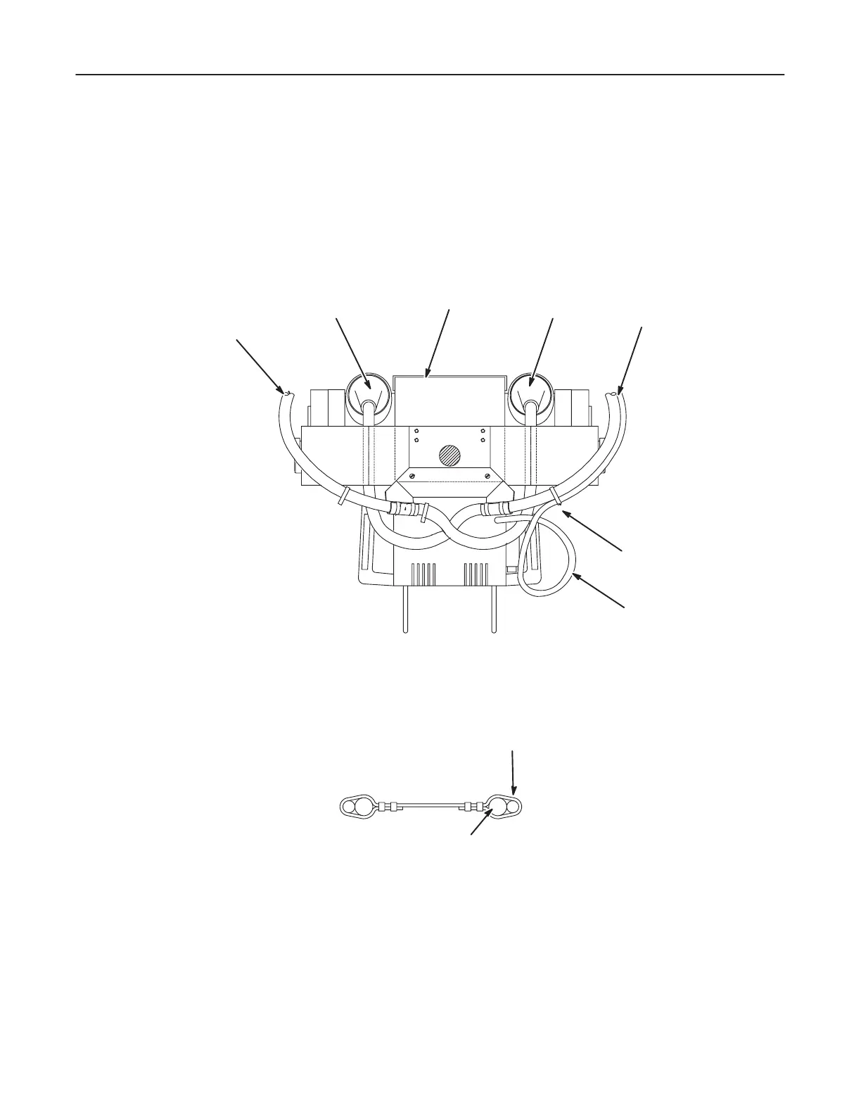
Collimator Cable
1. The collimator cable starts at the collimator, passes over the anode cable and
goes to strap point J" where it is joined to the cathode cable. There is a large loop
of cable before reaching strap point J" as shown in Illustration 10-9.
ILLUSTRATION 10-9
ANODE
CABLE
CATHODE
TUBE
STRAP POINT J"
COLLIMATOR CABLE
ANODE
CATHODE
CABLE
2. Continue routing and tyĆrapping the collimator cable along the cathode cable to
strap point C." See Illustration 10-10.
ILLUSTRATION 10-10
CATHODE
CABLE
COLLIMATOR
CABLE