REV 5 DIRECTION 2173225-100
10-7
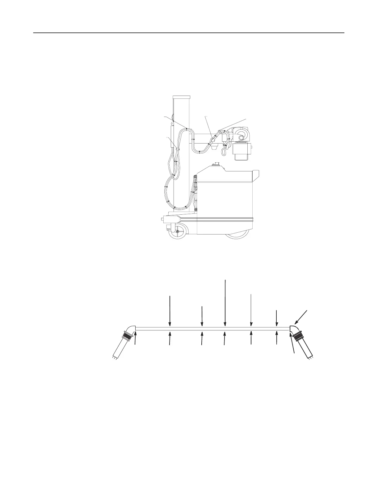
2. From clamp point L" the cable continues to strap point N" and clamp point
D." See Illustration 10-7.
ILLUSTRATION 10-7
CLAMP POINT A
STRAP POINT C
STRAP POINT N
CLAMP POINT D
D The distance from the tube to each clamp and strap point is shown in IllustraĆ
tion 10-8.
ILLUSTRATION 10-8
CLAMP POINT L"
CLAMP POINT A"
CLAMP POINT D"
TUBE END
"0"
17.0049.0090.00
STRAP POINT C"
83.00
STRAP POINT N"
41.00
176.00
REF
3. The anode cable continues from clamp point D" to strap point C," to point A"
and then to the front panel in a figure-eight configuration, then terminates at
the transformer in the base of the unit.

 Loading...


