7-3
Bumper Bearings Removal
This procedure covers the removal of any one or more of the eight bearings
comprising the bumper assembly.
1. Remove the bumper pads. Refer to Section 7Ć1Ć1.
2. Remove the bumper switches. Refer to Section 7Ć1Ć3.
3. Remove spring from between actuator bracket and spring bracket to release tenĆ
sion on switch actuator. See Illustration 7-2.
4. Remove switch actuator bracket by removing binding head screws and hex nuts.
5. Slide track from end of bumper assembly to expose bearings.
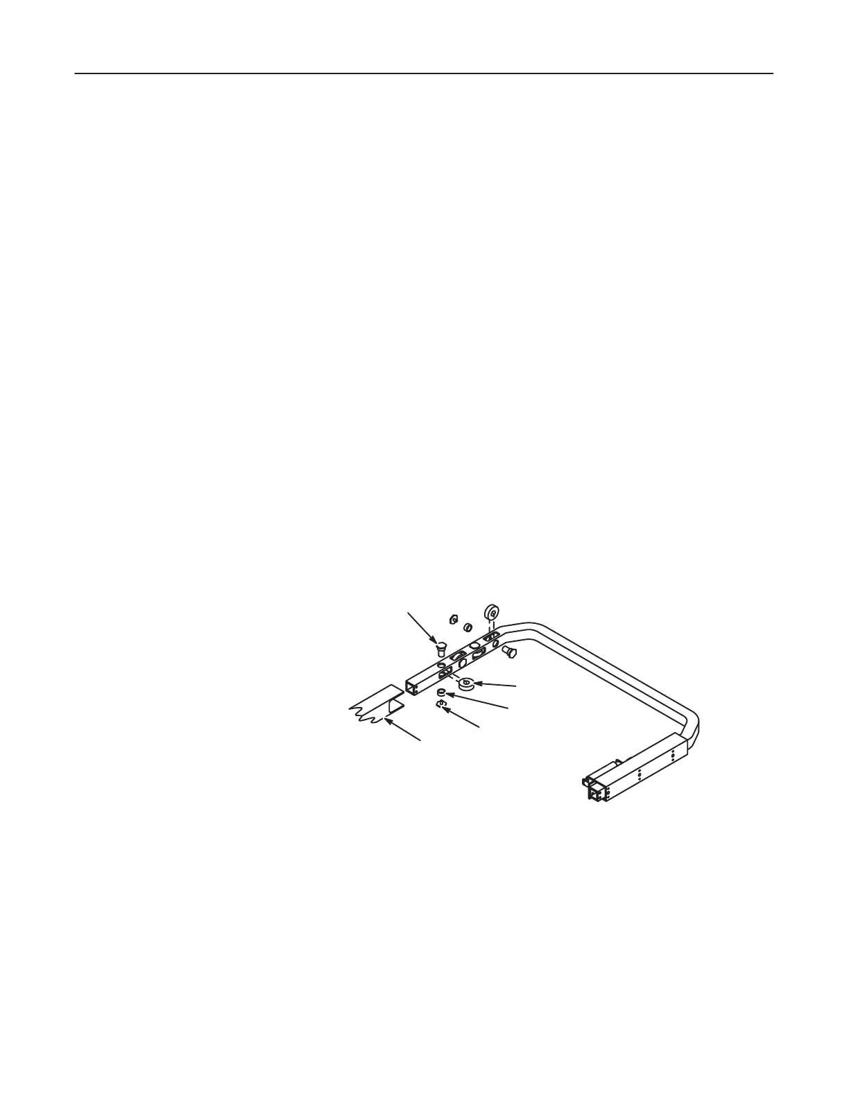
6. Remove bearing from mounting slot in bumper by removing hex head screw,
spacer and shaft.
Bumper Bearings Installation
This procedure covers the removal of any one or more of the eight bearings
comprising the bumper assembly.
1. Install bearing in bumper assembly mounting slot and secure with one hex head
screw, spacer and shaft. See Illustration 7-3.
ILLUSTRATION 7-3
2. Slide track into end of bumper assembly.
3. Install switch actuator bracket and secure with two binding head screws and hex
nuts.
4. Install spring between actuator bracket and spring bracket.
5. Verify that bumper switch is activated by spring tension on switch actuator
bracket.
6. Install the bumper assembly. Refer to Section 6-6.