REV 5 DIRECTION 2173225-100
4-26
#
" !
1. Remove vertical column assembly. Refer to Section 4-1.
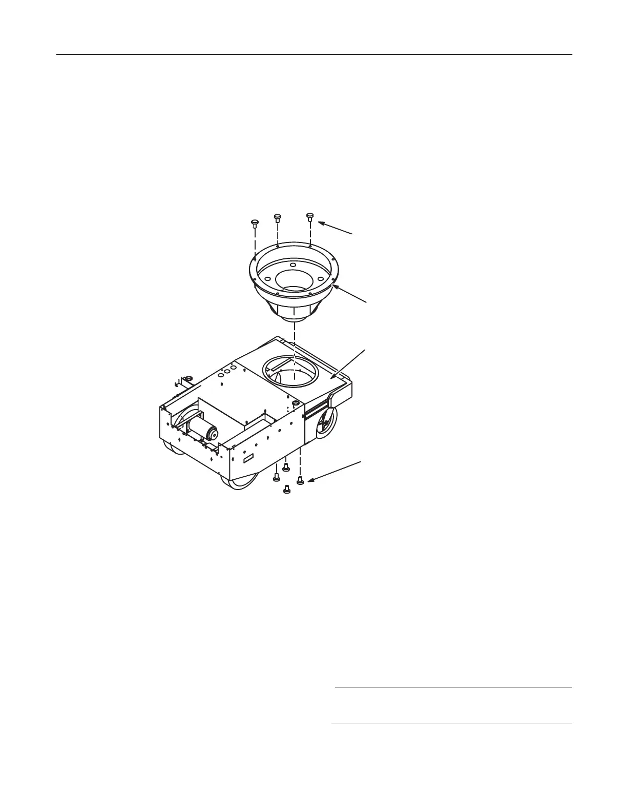
2. From beneath the bare assembly, remove capscrews and washers securing colĆ
umn support to bottom of base assembly. See Illustration 4-15.
ILLUSTRATION 4-15
CAPSCREWS(8)
LOCK WASHERS(8)
FLAT WASHERS(8)
TORQUE TO 100-120 LB. INS.
(11.2 TO 13.4 N-M)
BASE ASSEMBLY
COLUMN SUPPORT
LOCKWASHERS (4)
CAPSCREWS(4)
TORQUE TO 100-120 LB. INS.
(11.2 TO 13.4 N-M)
3. Remove hex head capscrews, lockwashers and flat washers securing the column
support to the base assembly.
4. Remove column support from base assembly.
#
"
1. Place column support in base assembly. Orient opening in side of column support
so it is opposite terminal board in base assembly. Line up mounting holes. See
Illustration 4-15.
2. Secure the column support to the base assembly with hex head capscrews, lockĆ
washers and flat washers. Torque to 100-120 pound-inches (11.2 to 13.4 N-m).
3. Secure bottom of column support to bottom of front tongue in base assembly with
cap screws and washers. Torque to 100-120 pound-inches (11.2 to 13.4 N-m).
4. Install vertical column assembly. Refer to Section 4-2.