1-1
This section provides procedures covering the removal and installation of the collimaĆ
tor. It also provides procedures for replacing and aligning the field lamp, aligning the
crosshairs, and replacing the brake and field lamp switches.
5 *''%(/*- !(*1'
1. Close collimator blades.
2. Rotate X-ray tube and collimator assembly so collimator crosshair window is
facing upward.
3. Place the horizontal arm assembly in park position on top cover of unit.
,0%+(!)/ (#!
!0-! /$! $*-%4*)/' -( !"*-! -!(*1%)# *(+*)!)/. "-*( /$! -( !5
(*1%)# 2!%#$/ ''*2. /$! *0)/!-2!%#$/ /* !.!) -+% '3 ) /$! -( /* .5
!) -+% '3 +*..%'3 0.%)# (#! /* /$! 0)%/ ) +!-.*)' %)&0-3 .!
*0)/!-2!%#$/ %"/ **'
4. Shut off power by turning circuit breaker OFF.
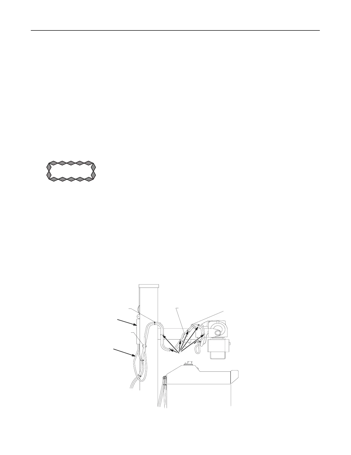
5. Remove two screws in bottom of terminal box located on back of vertical column
and lift off cover. See Illustration 1-1.
6. Disconnect collimator cable leads from terminal block. Record and tag leads.
7. Remove Heyco bushing and cable through bottom of terminal box.
ILLUSTRATION 1-1
CLAMP POINT E
STRAP POINT G
STRAP POINT N
CLAMP POINT H
TERMINAL BOX
COLLIMATOR CABLE
TIE WRAPS

 Loading...


