5-3
1. Turn power off by turning circuit breaker OFF.
This procedure covers the installation of both the right and left trim covers.
2. Install side covers by first pressing the five ball studs into retainer sockets on base
and mainframe assemblies. See Illustration 5-2.
3. Secure each side cover to base and mainframe assemblies with two 4-40 x 3/8
inch binding head screws and one 6-32 x 1/2 inch black oxide binding head screw.
4. Connect handswitch on right side trim cover.
5. Install rear cover with two screws.
6. Install front cover on unit by pressing ball studs on corners of cover into retainer
sockets.
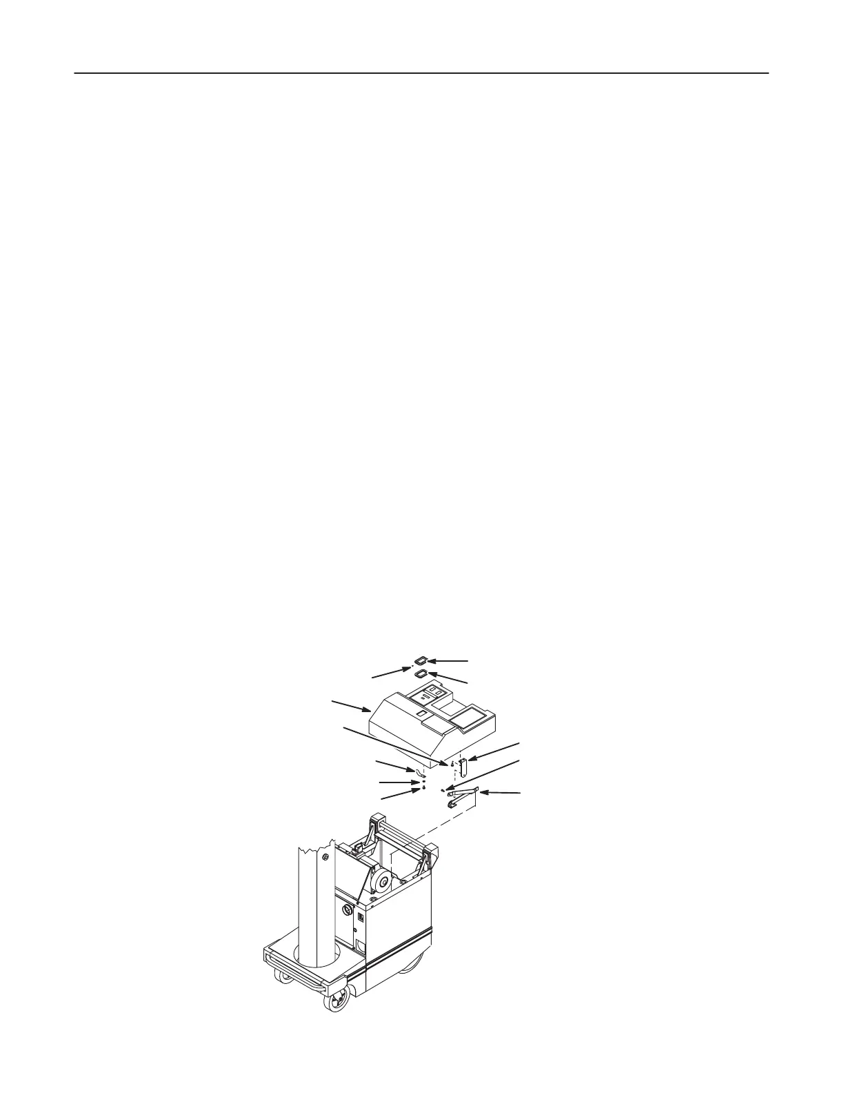
1. Move horizontal arm to top of column.
2. Turn power off by turning circuit breaker OFF.
3. Open cassette drawer, reach up into top cover and rotate two spring latches to
release cover from the mainframe.
4. Remove three hex socket capscrews holding collar to horizontal arm latch and lift
off collar and spacer beneath it. See Illustration 5-3.
ILLUSTRATION 5-3