EasyManuals Logo

GE AMX 4+ Technical Manual

GE AMX 4+
132 pages
To Next Page IconTo Next Page
To Previous Page IconTo Previous Page
Page #49 background imageLoading...
Page #49 background image
 
        
  
4-1

   
This section provides procedures covering the removal and installation of the field
serviceable assemblies subassemblies and parts comprising the vertical column assemĆ
bly.
"     !
1. Remove x-ray tube, collimator, and horizontal arm assemblies per Section 3-5.
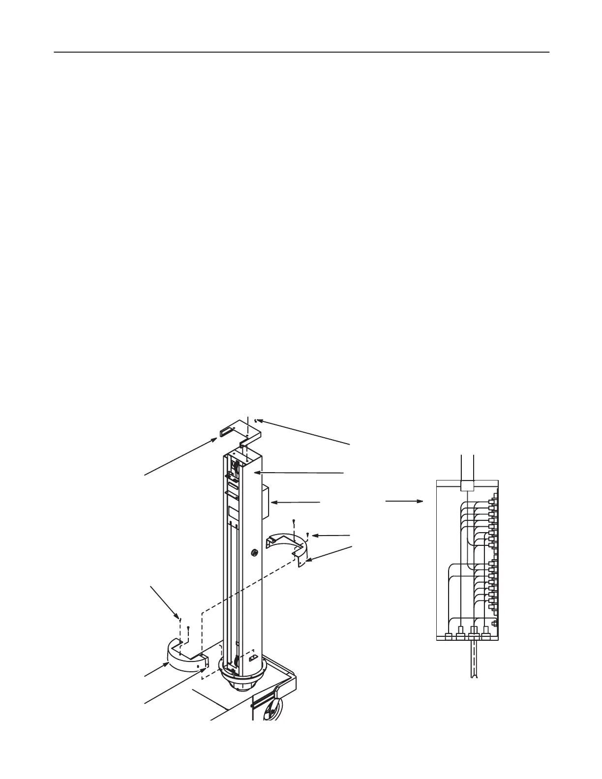
2. Disconnect control cable leads from terminal block. Record and tag leads. See
Illustration 4-1.
3. Remove Heyco bushing and cable through bottom of terminal box.
4. Clear all cables and wires from the column area.
5. Remove vertical column cap by removing two hex socket button head capscrews.
See Illustration 4-1.
6. Attach lifting tool (46-303362P1) to top of column with 2 screws.
7. Attach chain hoist to lifting tool (46-303362P1) and take up slack.
D The chain hoist must be capable of lifting a seven foot (2.1 meter), 175 lb.
(80 kg) column a minimum of two feet (61 cm), preferably 4 feet (122 cm)..
ILLUSTRATION 4-1
   










 
 

 

Table of Contents

Other manuals for GE AMX 4+

Questions and Answers:

Question and Answer IconNeed help?

Do you have a question about the GE AMX 4+ and is the answer not in the manual?

GE AMX 4+ Specifications

General IconGeneral
TypeMobile X-ray System
Maximum kVp125 kVp
CollimatorManual Collimator
BatteryRechargeable, lead-acid
Image Receptor CompatibilityCR and DR systems
Focal Spot Size1.2 mm
mAs Range0.04 - 320 mAs
X-ray TubeRotating Anode

Related product manuals