8-4
$ "
#! "
! This procedure covers removal of either the right or left enable switch from
the handle assembly.
1. Open top cover and place in position to easily access the handle assembly. Refer
to Section 5-5.
2. Cut ty-raps holding drive enable switch leads to end casting angle support brackĆ
et. See Illustration 8-1.
3. Free the drive enable switch leads from the other wires. (blue, yellow or gray -
positions 1&2inconnector) See Illustration 8-2.
4. Disconnect drive enable switch leads from connector.
5. Remove end cap from end casting by removing four hex socket button head
capscrews. See Illustration 8-3.
6. Slide end cap along handle away from end casting to allow access to drive enable
switch.
7. Pull switch leads through back of end casting.
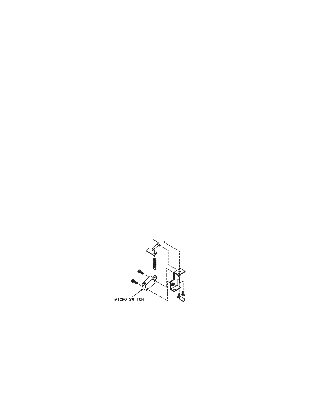
8. See Illustration 8-4 for the drive enable microswitch.
9. Remove two screws securing drive enable microswitch to bracket, and remove
this microswitch.
ILLUSTRATION 8-4

 Loading...


