REV 5 DIRECTION 2173225-100
10-5
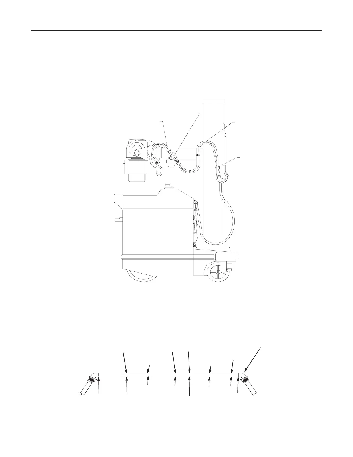
2. From clamp K" the cable continues to strap point M" and then to clamp point
H." See Illustration 10-4.
ILLUSTRATION 10-4
CLAMP POINT E
CLAMP POINT H
STRAP POINT M
STRAP POINT G
3. The cathode cable continues from clamp point H" and strap point G," to clamp
point E" to the front panel in a figure-eight configuration, and then terminates
at the transformer in the base of the unit.
D The distances are referenced in Illustration 10-5.
ILLUSTRATION 10-5
CLAMP
POINT K"
17.00
CLAMP
POINT E"
STRAP
POINT G"
CLAMP
POINT H"
TUBE END
"0"
19.7549.0083.00
90.00
41.00
STRAP
POINT M"
STRAP
POINT J"
176.00
REF
Strap point J" is installed with collimator cable.

 Loading...


