EasyManuals Logo

GE AMX 4+ Technical Manual

GE AMX 4+
132 pages
To Next Page IconTo Next Page
To Previous Page IconTo Previous Page
Page #80 background imageLoading...
Page #80 background image
 
        
  
5-6
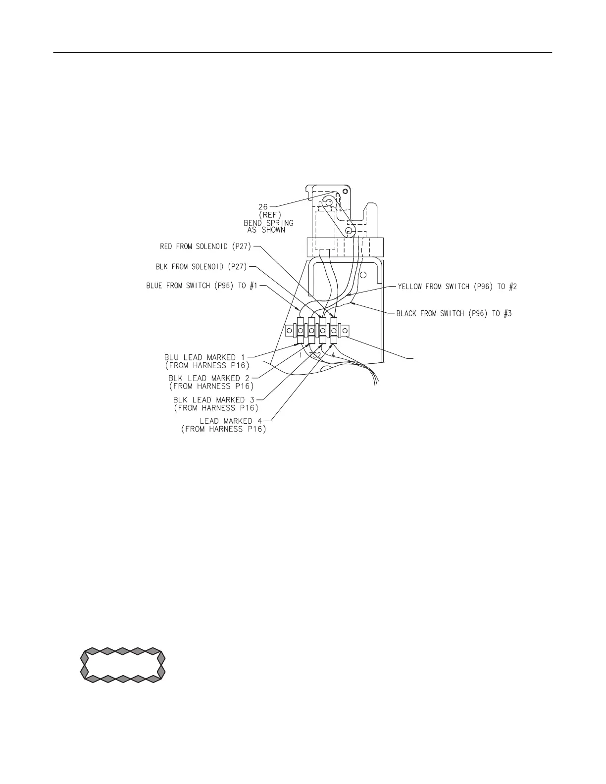
4. Disconnect leads from terminal strip (see Illustration 5-5):
D Sensor Board: three leads to quick disconnect connectors. (#1, #2 and #3).
D Solenoid: two leads to terminal strip. Tag and label terminals. Must reconĆ
nect properly on #3 & #4 or will blow diode in solenoid.
ILLUSTRATION 5-5
 
TERMINAL STRIP
WHITE
5. Remove latch assembly from mainframe by removing four hex socket head
capscrews.
6. Remove latch block from spacer by removing four hex socket head capscrews.
7. Push spring pin out of latch block.
8. Remove latch.
9. Remove latch spring by removing binding head screw.
10. Remove hex nut from top of solenoid.
11. Remove solenoid from recess in latch block.
12. Remove the two flat head screws in side of latch base.
             !
 
13. Remove the cover and the Hall effect sensor circuit board.


Table of Contents

Other manuals for GE AMX 4+

Questions and Answers:

Question and Answer IconNeed help?

Do you have a question about the GE AMX 4+ and is the answer not in the manual?

GE AMX 4+ Specifications

General IconGeneral
TypeMobile X-ray System
Maximum kVp125 kVp
CollimatorManual Collimator
BatteryRechargeable, lead-acid
Image Receptor CompatibilityCR and DR systems
Focal Spot Size1.2 mm
mAs Range0.04 - 320 mAs
X-ray TubeRotating Anode

Related product manuals