REV 5 DIRECTION 2173225-100
7-5
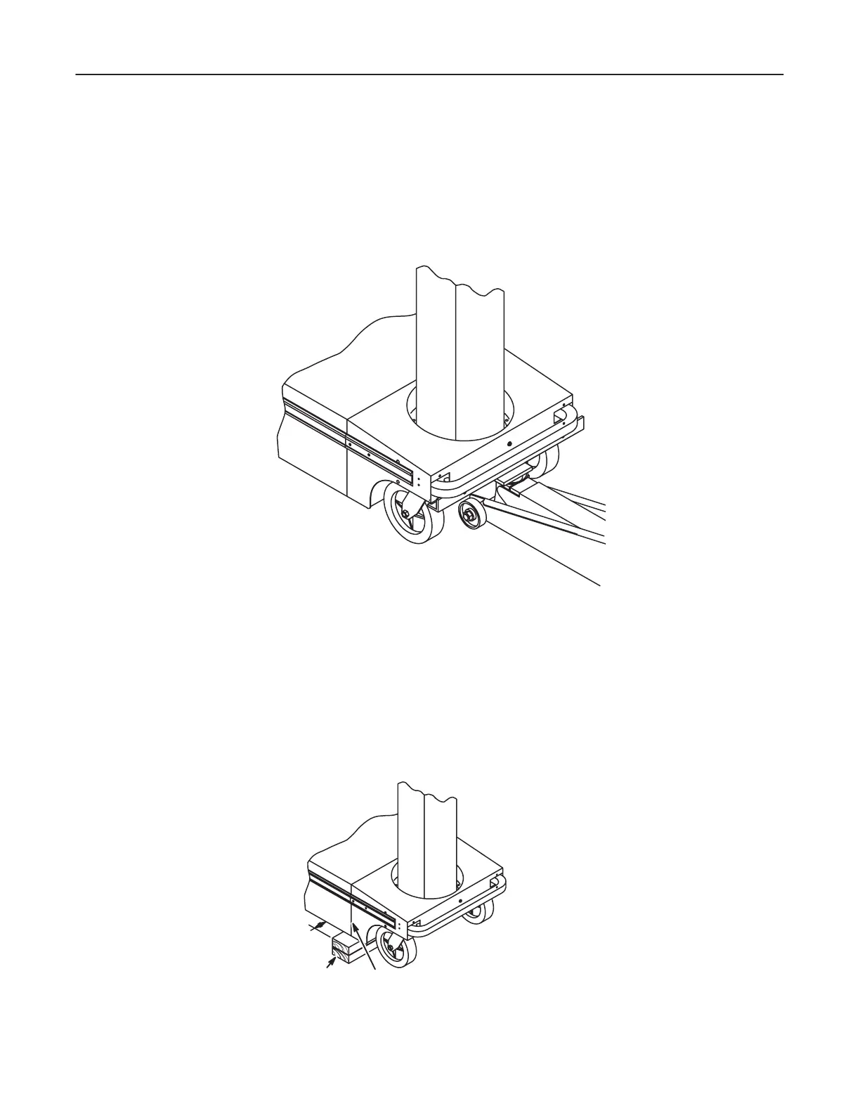
Raise Front Wheels
1. Remove front bumper pads. Refer to Section 7Ć1Ć1.
2. Put the jack under the front of the AMX unit. See Illustration 7-5.
ILLUSTRATION 7-5
3. Lift the AMX unit high enough to put the wood block (one 4x4 inch or two 2x4
inch) under the AMX unit as shown in Illustration 7-6. Be sure that the block(s)
is (are) centered under the front battery box wall, and be sure that the block(s)
extend(s) out at least 2 inches (5 cm) on each side of AMX unit.
ILLUSTRATION 7-6
2 INCHES
(5 cm) MIN.
WOOD BLOCK(S)
(SEE NOTES 1, 2, & 3)
FRONT BATTERY
BOX WALL
NOTE 1: IF TWO BLOCKS ARE USED, ORIENT
BLOCKS FOR MAXIMUM STABILITY.
NOTE 2: CENTER BLOCK(S) WITH FRONT
BATTERY BOX WALL.
NOTE 3: LOCATE WOOD BLOCK(S) SO THAT
BLOCK(S) STICKS OUT AT LEAST 2
INCHES (5 cm) BEYOND EACH SIDE
OF THE AMX UNIT.