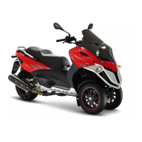
3: TILT LOCKING-UNLOCKING SWITCH
With interface wiring disconnected from the control
unit, check the continuity of the electrical lines be-
tween the interface wiring and the tilt locking-un-
locking switch:
Pin 26 and green - grey cable
Pin 35 and violet - black cable
Pin 33 and yellow - blue cable
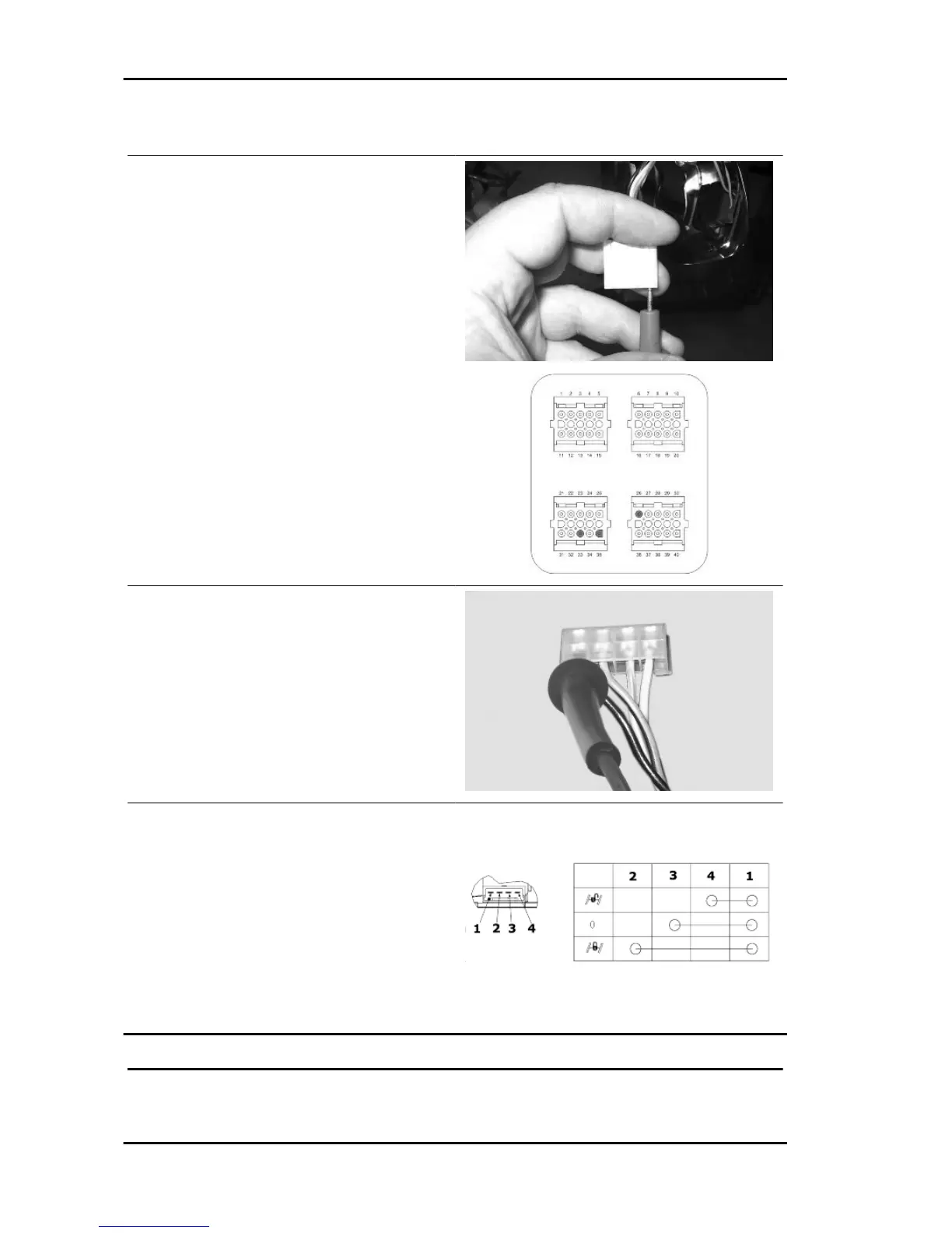
Also check that the above indicated electrical lines
are insulated from the earth.
Check the continuity between the black cable on
the connector and an earth point on the chassis.
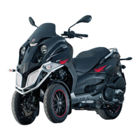
With a multimeter, check the operation of the tilt
locking-unlocking switch referring to the diagram
indicated in the figure.
KEY
1. GROUND
2. LOCKING
3. REST
4. UNLOCKING
TILT LOCKING CALLIPER SENSOR
Suspensions Fuoco 500 i.e.
SUSP - 34