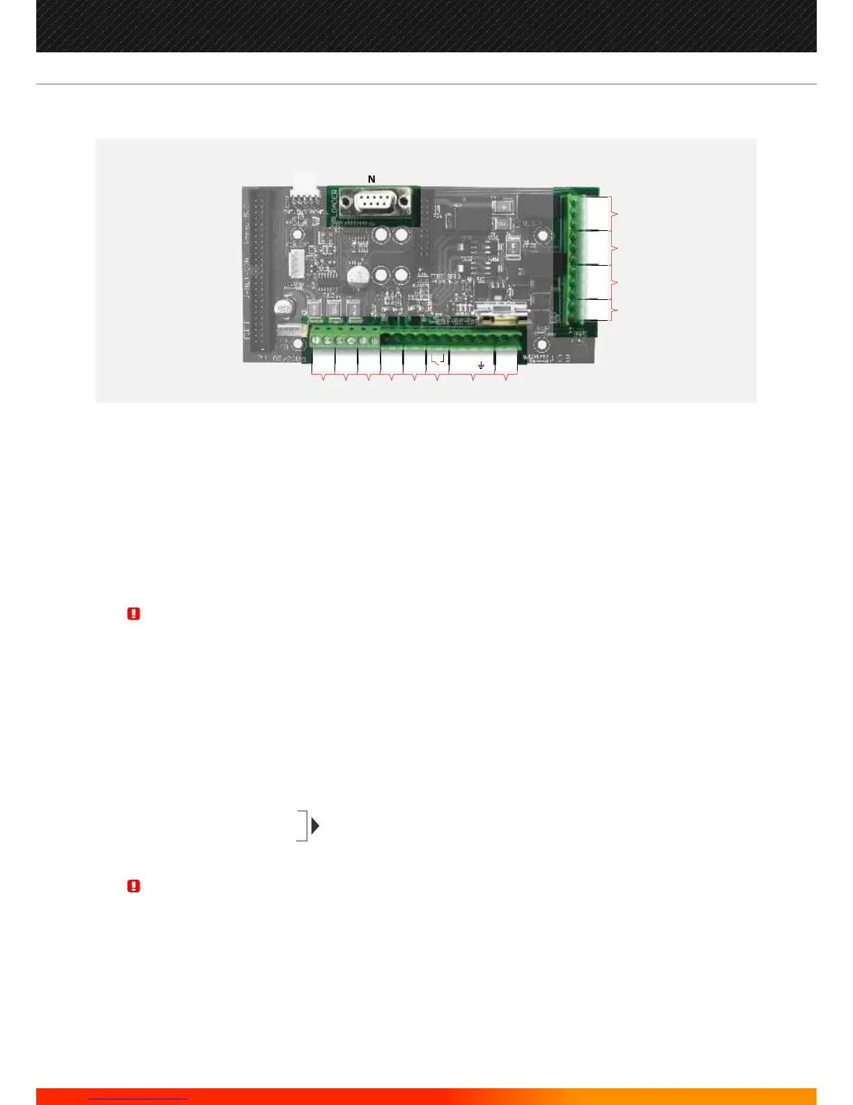
J-NET-CON
Auxiliary power supply output for powering external devices
Auxiliary power supply output for powering external devices
Both auxiliary power supply outputs are individually power limited and supervised
Max. Current Rating/ Output is 230 mA b@ 27.5 V DC nominal
Zone multiplex output for zone or mimic panel
Conventional Sounder Circuit 1
Conventional Sounder Circuit 2
Each Conventional Sounder Circuit is current limited and monitored for both open and short circuit fault conditions. The use in each circuit of
a 10 K ohms E.O.L. resistor is required.
Max. Current Rating/ Output is 400 mA @ 27.5 V DC nominal.
Remote Evacuation / Class Change Input. (Conventional sounder outputs only)
System Power Input (pre-wired and monitored)
Battery Connection
Earth Point
Auxiliary Fault Relay Output. (Activated by any fault present on the system)
This relay output will remain closed while there are no faults present in the system. Under any fault condition present, the relay will be de-
energised and the relay contact will be open.
Auxiliary Fire Relay Output 2
Auxiliary Fire Relay Output 1
Under the presence of any Fire Alarm condition, these 2 relays will be energised. Both set of contacts are of the change-over type. Max.
Contact current rating for each set of relay contacts is 1 Amp @ 50 V AC/DC resistive.
Pre-alarm, Fault and Fire, Open Collector Outputs
Loader Interface: For Upload/Download Software
CON 1: Used to connect to other sub-panels within a self-contained panel
CON 5: Used for connecting RS485 , Fibre-Optic, and TCP/IP
CON 2: Used for MPX, Zone LEDs
The total current load of all detection loops, sounder circuits and auxiliary supply outputs should not exceed the maximum
power rating of the panel. Please refer to technical specification tables.
Relay outputs are not supervised. Please ensure that any wiring connected to these outputs is power limited.
WARNING:
WARNING:
A
B
C
D
E
F
G
H
I
J
K
L
M
N
O
P
Q
(Activated by any fire situation present
on the system, disabled by front button)
N
J
K
M
L
PAL
NO
NO
FIR
NC
NC
NC
REPEATSAUX 2FAULT AUX 1
FLT
C
C
C
A B
C D E F
HG
AUX 1
PSU
AUX 2
PSU
BELL 1 BELL 2
24v
BATT
EVAC
ZONE
MPX
OUT PF E SF24v0v 0v
0v
+ - + - + - + - + -
24
Manufacturers of Fire Detection Equipment
INSTALLATION & COMMISSIONING MANUAL REVISION 4.0 05/2013
JUNO NET - NETWORKABLE ADRESSABLE PANEL
globalfire.pt